HP Dv6 1240us Service Guide - Page 72
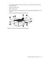
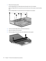
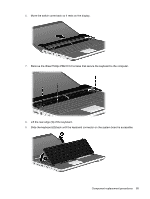
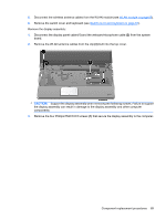
Open the computer as far as possible.
 |
UPC - 884962256473
View all HP Dv6 1240us manuals
Add to My Manuals
Save this manual to your list of manuals |
Page 72 highlights
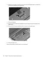
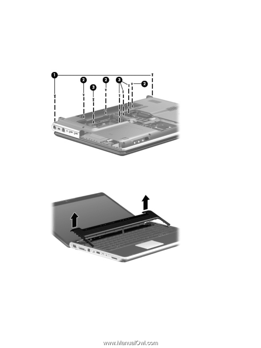
2. Remove the following screws: (1) Two Phillips PM2.5×6.5 screws that secure the switch cover to the computer (2) Three Phillips PM2.5×5.0 screws that secure the switch cover to the computer (inside the battery bay) (3) Four Phillips PM2.5×6.5 screws that secure the keyboard to the computer 3. Turn the computer display-side up, with the front toward you. 4. Open the computer as far as possible. 5. Lift the rear edge of the switch cover until it detaches from the computer. 64 Chapter 4 Removal and replacement procedures
-
 1
1 -
2
-
3
-
4
-
5
-
6
-
7
-
8
-
9
-
10
-
11
-
12
-
13
-
14
-
15
-
16
-
17
-
18
-
19
-
20
-
21
-
22
-
23
-
24
-
25
-
26
-
27
-
28
-
29
-
30
-
31
-
32
-
33
-
34
-
35
-
36
-
37
-
38
-
39
-
40
-
41
-
42
-
43
-
44
-
45
-
46
-
47
-
48
-
49
-
50
-
51
-
52
-
53
-
54
-
55
-
56
-
57
-
58
-
59
-
60
-
61
-
62
-
63
-
64
-
65
-
66
-
 67
67 -
 68
68 -
 69
69 -
 70
70 -
 71
71 -
 72
72 -
 73
73 -
 74
74 -
 75
75 -
 76
76 -
 77
77 -
78
-
79
-
80
-
81
-
82
-
83
-
84
-
85
-
86
-
87
-
88
-
89
-
90
-
91
-
92
-
93
-
94
-
95
-
96
-
97
-
98
-
99
-
100
-
101
-
102
-
103
-
104
-
105
-
106
-
107
-
108
-
109
-
110
-
111
-
112
-
113
-
114
-
115
-
116
-
117
-
118
-
119
-
120
-
121
-
122
-
123
-
124
-
125
-
126
-
127
-
128
-
129
-
130
-
131
-
132
-
133
-
134
-
135
-
136
-
137
-
138
-
139
-
140
-
141
-
142
-
143
-
144
-
145
-
146
-
147
-
148
-
149
-
150
-
151
-
152
-
153
-
154
-
155
-
156
-
157
-
158
-
159
-
160
-
161
-
162
-
163
-
164
-
165
-
166
 |
 |
2.
Remove the following screws:
(1)
Two Phillips PM2.5×6.5 screws that secure the switch cover to the computer
(2)
Three Phillips PM2.5×5.0 screws that secure the switch cover to the computer (inside the battery
bay)
(3)
Four Phillips PM2.5×6.5 screws that secure the keyboard to the computer
3.
Turn the computer display-side up, with the front toward you.
4.
Open the computer as far as possible.
5.
Lift the rear edge of the switch cover until it detaches from the computer.
64
Chapter 4
Removal and replacement procedures