HP Dv6810us HP Pavilion dv6500, dv6600, and dv6700 Entertainment PCs - Mainten - Page 84
Two Phillips PM2.5×7.0 screws
 |
UPC - 883585926985
View all HP Dv6810us manuals
Add to My Manuals
Save this manual to your list of manuals |
Page 84 highlights
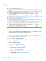
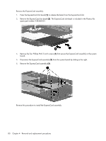
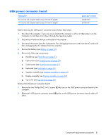
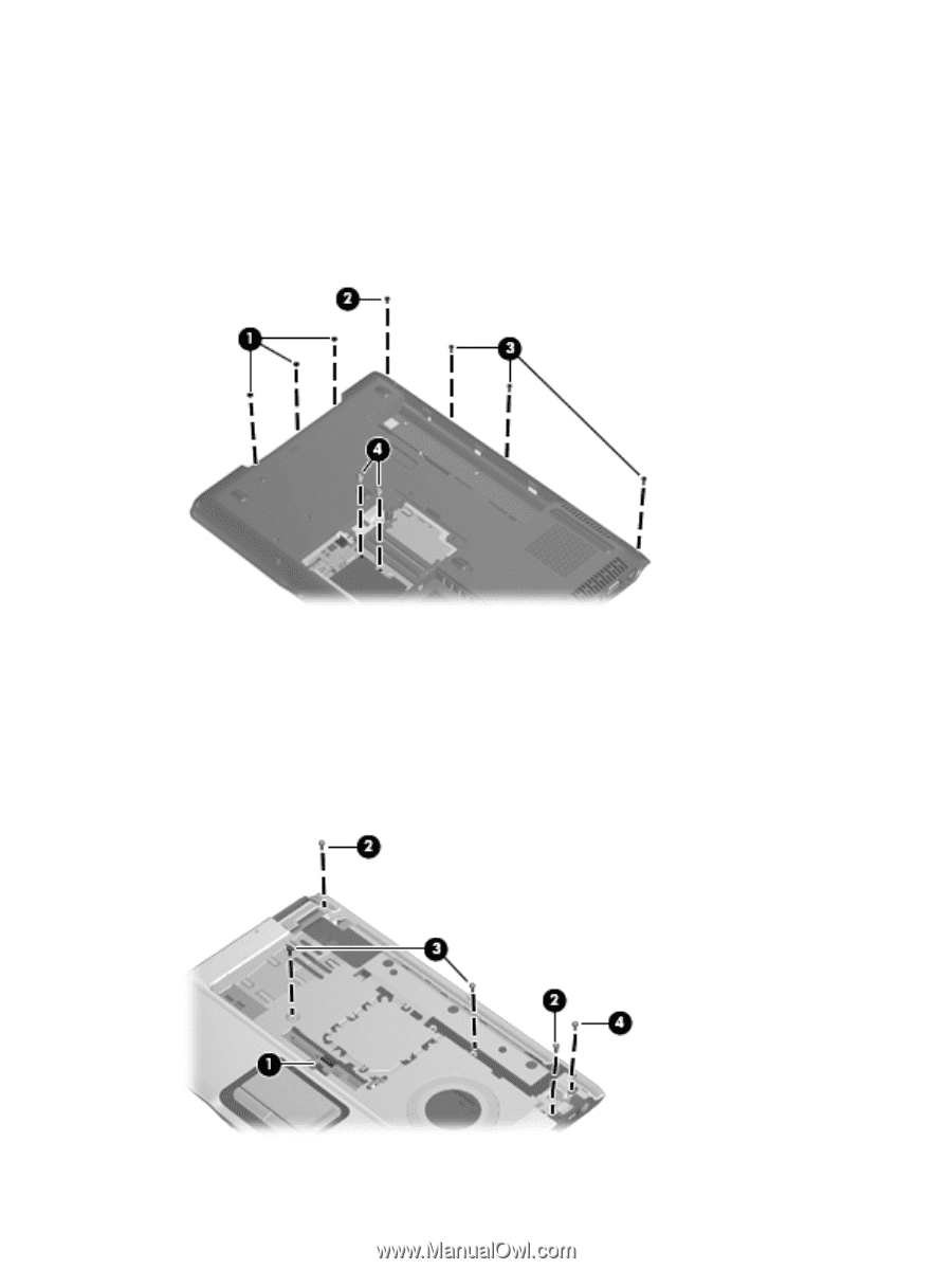
6. Remove the following: (1) Three Phillips PM2.5×2.0 screws in the optical drive bay (2) One Phillips PM2.5×5.0 screw on the rear edge of the base enclosure (3) Three Phillips PM2.5×7.0 screws on the rear edge of the base enclosure that secure the top cover trim to the computer (4) Two HM5.0×9.0 standoffs in the memory/WLAN module compartment 7. Turn the computer right-side up, with the front toward you. 8. Release and disconnect the TouchPad cable (1) from the ZIF connector on the system board. 9. Remove the following screws: (2) Two Phillips PM2.5×7.0 screws (3) Two Phillips PM2.5×4.0 screws (4) One Phillips PM2.5×5.0 screw that secures the top cover trim to the computer 76 Chapter 4 Removal and replacement procedures
-
 1
1 -
2
-
3
-
4
-
5
-
6
-
7
-
8
-
9
-
10
-
11
-
12
-
13
-
14
-
15
-
16
-
17
-
18
-
19
-
20
-
21
-
22
-
23
-
24
-
25
-
26
-
27
-
28
-
29
-
30
-
31
-
32
-
33
-
34
-
35
-
36
-
37
-
38
-
39
-
40
-
41
-
42
-
43
-
44
-
45
-
46
-
47
-
48
-
49
-
50
-
51
-
52
-
53
-
54
-
55
-
56
-
57
-
58
-
59
-
60
-
61
-
62
-
63
-
64
-
65
-
66
-
67
-
68
-
69
-
70
-
71
-
72
-
73
-
74
-
75
-
76
-
77
-
78
-
 79
79 -
 80
80 -
 81
81 -
 82
82 -
 83
83 -
 84
84 -
 85
85 -
 86
86 -
 87
87 -
 88
88 -
 89
89 -
90
-
91
-
92
-
93
-
94
-
95
-
96
-
97
-
98
-
99
-
100
-
101
-
102
-
103
-
104
-
105
-
106
-
107
-
108
-
109
-
110
-
111
-
112
-
113
-
114
-
115
-
116
-
117
-
118
-
119
-
120
-
121
-
122
-
123
-
124
-
125
-
126
-
127
-
128
-
129
-
130
-
131
-
132
-
133
-
134
-
135
-
136
-
137
-
138
-
139
-
140
-
141
-
142
-
143
-
144
-
145
-
146
-
147
-
148
-
149
-
150
-
151
-
152
-
153
-
154
-
155
-
156
-
157
-
158
-
159
-
160
 |
 |
6
.
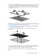
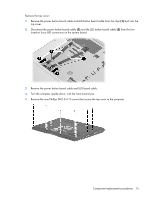
Remove the following:
(1)
Three Phillips PM2.5×2.0 screws in the optical drive bay
(2)
One Phillips PM2.5×5.0 screw on the rear edge of the base enclosure
(3)
Three Phillips PM2.5×7.0 screws on the rear edge of the base enclosure that secure the top cover
trim to the computer
(4)
Two HM5.0×9.0 standoffs in the memory/WLAN module compartment
7
.
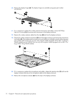
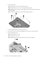
Turn the computer right-side up, with the front toward you.
8
.
Release and disconnect the TouchPad cable
(1)
from the ZIF connector on the system board.
9
.
Remove the following screws:
(2)
Two Phillips PM2.5×7.0 screws
(3)
Two Phillips PM2.5×4.0 screws
(4)
One Phillips PM2.5×5.0 screw that secures the top cover trim to the computer
76
Chapter
4
Removal and replacement procedures