HP Dx2250 HP Compaq dx2250 Microtower Business PC - Illustrated Parts & Se - Page 3
System Board, System Setup and Boot, Computer Setup Menu - bios flash
 |
UPC - 883585243983
View all HP Dx2250 manuals
Add to My Manuals
Save this manual to your list of manuals |
Page 3 highlights
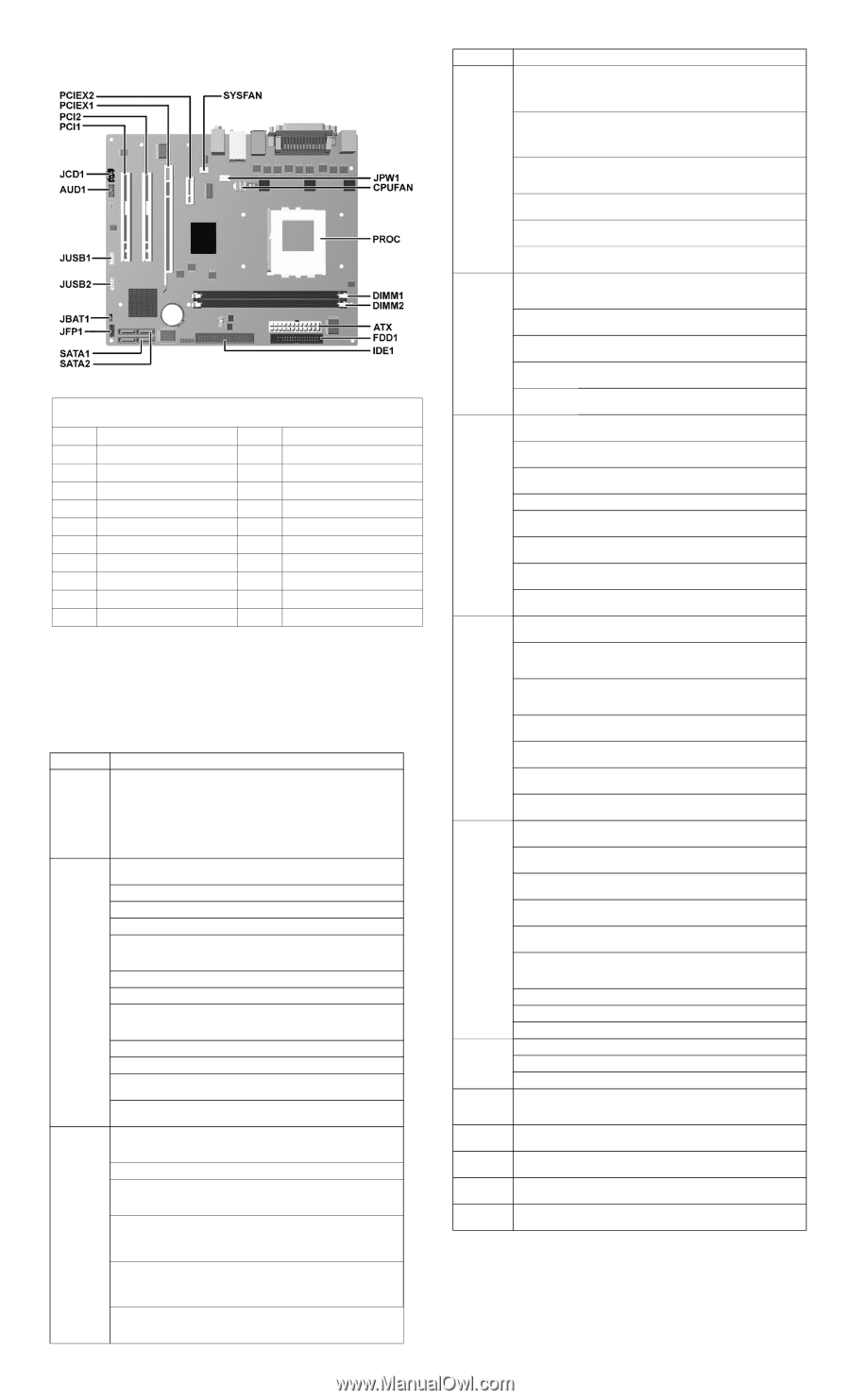
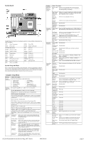
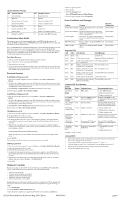
System Board System Board Connectors and Jumpers (position of some untitled components may vary in location) ATX Main 24-pin power JUSB1 Front USB AUD1 Front audio JUSB2 Media Card Reader CPUFAN Heatsink fan PCI1 PCI card DIMM1 Memory module PCI2 PCI card DIMM2 Memory module PCIEX1 PCI-E x1 FDD1 Diskette drive PCIEX2 PCI-E x16 IDE1 IDE drive SATA1 Serial ATA JBAT1 CMOS SATA2 Serial ATA JCD1 CD Audio (not used) SYSFAN Chassis fan JPW1 Aux power (4-pin) PROC Microprocessor JFP1 Power switch/LED System Setup and Boot Basic system information regarding system information, setup, power management, hardware, and passwords is maintained in the Setup Utility held in the system ROM. The Setup Utility is accessed by pressing the F10 key when prompted (on screen) to do so during the boot sequence. If the screen prompt opportunity is missed, a restart will be necessary. Computer Setup Menu Heading System Information Standard CMOS Features Advanced BIOS features Option / Description Lists the following main system specifications: • Product Name • SKU Number • Processor Type • Processor Speed • Cache Size • Memory Size • System ROM • Integrated MAC • UUID • System Serial # • Asset Tracking Number • Enter Asset Tag Number System Date (mm/dd/yyyy) - Allows you to set system date. System Time (hh/mm/ss) - Allows you to set system time. Floppy Drive A - Calculates size and capacity of diskette drive. PATA Controller - Disable/enable. PATA Channel 0 Master/PATA Channel 0 Slave - Allows you to run HDD self-tests, set device details, set access mode, and view information about the device(s) SATA Controller - Disable/enable SATA Mode - Allows you to set mode to Native/Legacy IDE SATA Channel 1 Master and Channel 2 Master - Allows you to run HDD self-tests, set device details, set access mode, and view information about the device(s) Floppy Controller - Disable/enable Drive A - Allows you to set to None or 1.4M, 3.5 in. Halt On - Allows you to set POST error behavior to: all errors, no errors, all but keyboard, all but diskette, or all but diskette/keyboard. POST Delay - Allows you to set POST delay to 0, 5, 10, 15, or 30 seconds Device Boot Disabling Allows you to restrict a device from booting the unit. May disable: none, USB, Internal ODD, Internal FDD, or USB+ODD+FDD F9 Boot Menu Disable/enable Removable device Boot Seq. Allows you to specify the order of attached removable devices. The first drive in the order has priority and is recognized as drive A. Hard Disk Boot Seq. Allows you to specify the order of attached hard drive devices (USB HDD, USB2 Drive Key, or USB flash media). The first attached drive in the order has priority and is recognized as drive C. Hard Disk Boot Seq. Allows you to specify the order of attached hard drive devices (USB HDD, USB2 Drive Key, or USB flash media). The first drive in the order has priority and is recognized as drive C (if attached). Optical Drive Allows you to specify the order in which attached opti- Boot Seq. cal drives (including USB ODD) are checked for a boot- able operating system image. Heading Option / Description Advanced BIOS features (continued) Network Boot Allows you to specify the order in which network Seq. devices (including UP NIC cards) are checked for a bootable operating system image. First, Second, Third, and Fourth Boot Device Allows you to specify which devices will boot in which sequence or to disable any of the four: removable, hard disk, CDROM, network, or disabled. Boot Up NumLock Status Allows you to set default to off or on. Security Option Allows you to set option to Setup or System. BIOS Write Disable/enable Protection AMD NX Function Disable/enable Advanced UMA Frame Select the UMA frame buffer size to: 32MB, 64MB, or Chipset Fea- Buffer Recommended (system automatically allocates memory) tures Init Display Allows you to select the primary display device: PCI First (VGA) slot, OnChip VGA, or PCIEx SURROUND- Disable/enable SURROUNDVIEW (when an ATI VIEW PCIEx video card is installed) (VGA setting) Auto Detect Disable/enable (VGA setting) PCI Clk Spread Spec- Disable/enable (VGA setting) trum Integrated Onboard HD Disable/enable Peripherals Audio OnChip USB Disable/enable Controller USB Legacy Disable/enable (USM mouse, keyboard, and flash Support media) Onboard LAN Disable/enable Onboard LAN Disable/enable Boot ROM Onboard Serial Port Select a setting: Disabled, 3F8/IRQ4, 2F8/IRQ3, 3E8/ IRQ4, or 2E8/IRQ3 Onboard Par- Select a setting: Disabled, 378/IRQ7, 278/IRQ5, or allel Port 3BC/IRQ7 Parallel Port Select a mode: SPP, EPP, ECP, ECP+EPP, or Normal Mode Power Management Setup After AC Power Loss External Modem S5 Wake-up Select system power loss behavior: On, Off, Last State Disable/enable Wake on PCI Disable/enable Device from S5 AMD Disable/enable Cool'n'Quiet RTC Alarm Disable/enable Resume Date (of Month) If RTC Alarm Resume is enabled, allows you to select any day of the month to resume RTC alarm. Resume Time If RTC Alarm Resume is enabled, allows you to select (hh:mm:ss) what time the RTC alarm will resume. PC Health System Fan Disable/enable Status Fail Check Smart Fan Function Disable/enable Current CPU View only Temperature Current Sys- View only tem Temp Current CPU View only Fan Speed Current System Fan Speed View only Vcore View only +12V View only VCC5 View only +3.3V View only VBAT (V) View only 3VSB (V) View only Action Choices Load Optimized Defaults Reset Computer Setup to factory defaults. Set Supervisor Allows you to establish a password to enter Computer Password Setup Set User Pass- Allows you to establish a password to enter the com- word puter (must have Supervisor password established) Exit & Save Save current settings and exit Computer Setup. Setup Exit Without Exit Computer Setup without saving changes. Saving dx2250 Illustrated Parts & Service Map, MT Chassis 440318-001 page 3
-
 1
1 -
 2
2 -
 3
3 -
 4
4
 |
 |