HP ENVY 15-3040nr HP ENVY 15 - Maintenance and Service Guide - Page 42
Component replacement procedures, Service tag
 |
View all HP ENVY 15-3040nr manuals
Add to My Manuals
Save this manual to your list of manuals |
Page 42 highlights
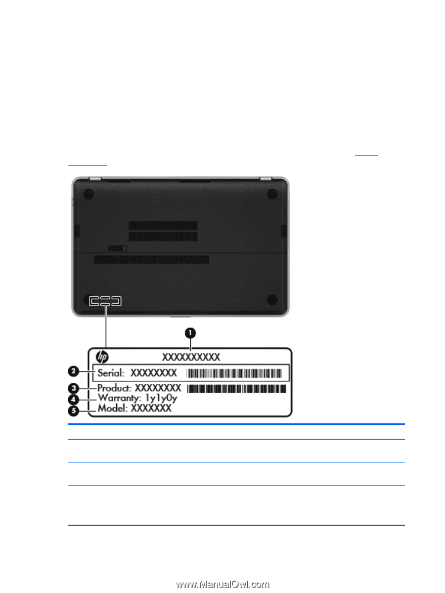
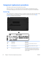
Component replacement procedures This chapter provides removal and replacement procedures. There are as many as 111 screws that must be removed, replaced, or loosened when servicing the computer. Make special note of each screw size and location during removal and replacement. Service tag When ordering parts or requesting information, provide the computer serial number and model number provided on the service tag. The battery must be removed to access the service tag. See Battery on page 35 for battery removal procedures. Item (1) (2) (3) Component Product name Serial number (s/n) Part number/Product number (p/n) Description This is the product name affixed to the front of the computer. This is an alphanumeric identifier that is unique to each product. This number provides specific information about the product's hardware components. The part number helps a service technician determine what components and parts are needed. 34 Chapter 4 Removal and replacement procedures ENWW
-
 1
1 -
2
-
3
-
4
-
5
-
6
-
7
-
8
-
9
-
10
-
11
-
12
-
13
-
14
-
15
-
16
-
17
-
18
-
19
-
20
-
21
-
22
-
23
-
24
-
25
-
26
-
27
-
28
-
29
-
30
-
31
-
32
-
33
-
34
-
35
-
36
-
 37
37 -
 38
38 -
 39
39 -
 40
40 -
 41
41 -
 42
42 -
 43
43 -
 44
44 -
 45
45 -
 46
46 -
 47
47 -
48
-
49
-
50
-
51
-
52
-
53
-
54
-
55
-
56
-
57
-
58
-
59
-
60
-
61
-
62
-
63
-
64
-
65
-
66
-
67
-
68
-
69
-
70
-
71
-
72
-
73
-
74
-
75
-
76
-
77
-
78
-
79
-
80
-
81
-
82
-
83
-
84
-
85
-
86
-
87
-
88
-
89
-
90
-
91
-
92
-
93
-
94
-
95
-
96
-
97
-
98
-
99
-
100
-
101
-
102
-
103
-
104
-
105
-
106
-
107
-
108
-
109
-
110
-
111
-
112
-
113
-
114
-
115
-
116
-
117
-
118
-
119
-
120
-
121
-
122
-
123
-
124
 |
 |