HP ENVY 17-1181nr HP ENVY 17 - Maintenance and Service Guide - Page 81
Display assembly
 |
View all HP ENVY 17-1181nr manuals
Add to My Manuals
Save this manual to your list of manuals |
Page 81 highlights
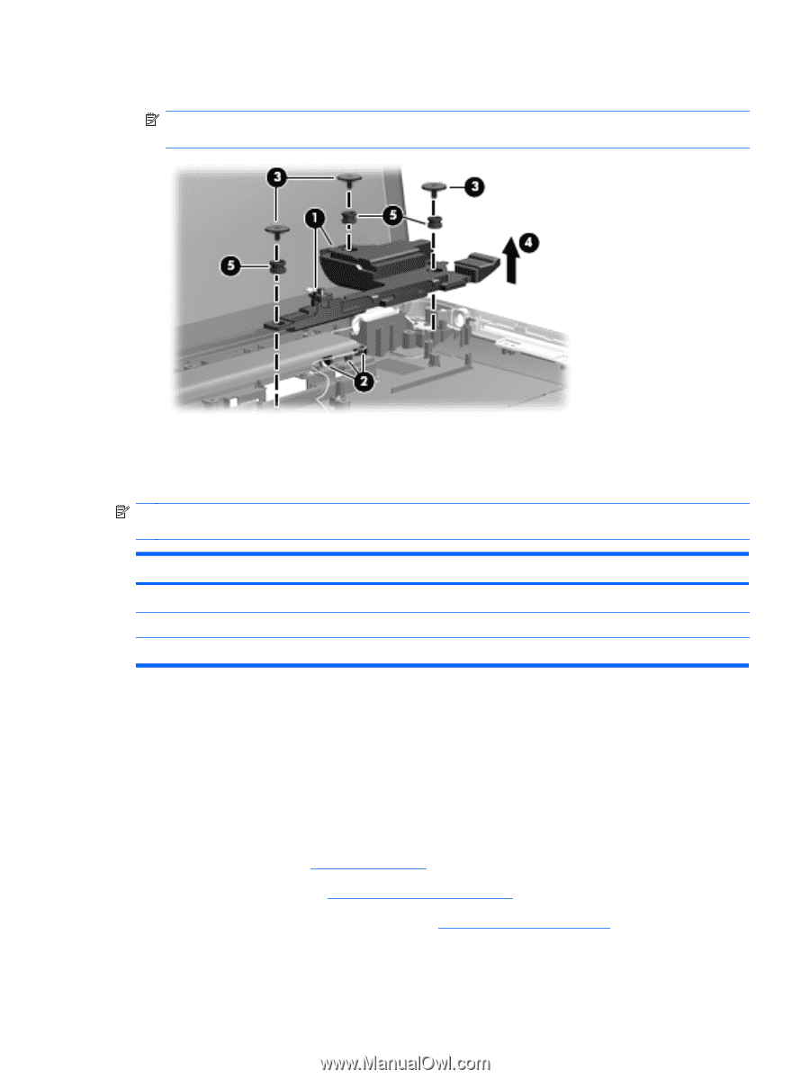
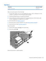
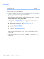
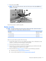
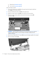
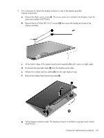
3. Remove the subwoofer (4). NOTE: When removing the subwoofer, make note of the location of the isolators (5) that are installed in screw holes. Reverse this procedure to install the subwoofer. Display assembly NOTE: The display assembly spare part kit includes a display panel cable, webcam/microphone module and cable, and 2 wireless antenna cables and transceivers. Description 17.3-in AG, FG, 3D 17.3-in AG, FG, FHD 17.3-in AG, FG, HD+ Spare part number 620775-001 603774-001 603773-001 Before removing the display assembly, follow these steps: 1. Shut down the computer. If you are unsure whether the computer is off or in Hibernation, turn the computer on, and then shut it down through the operating system. 2. Disconnect all external devices connected to the computer. 3. Disconnect the power from the computer by first unplugging the power cord from the AC outlet and then unplugging the AC adapter from the computer. 4. Remove the battery (see Battery on page 38), and then remove the following components: a. Hard drive cover (see Primary hard drive on page 39) b. memory module compartment cover (see Memory module on page 43). Component replacement procedures 71
-
 1
1 -
2
-
3
-
4
-
5
-
6
-
7
-
8
-
9
-
10
-
11
-
12
-
13
-
14
-
15
-
16
-
17
-
18
-
19
-
20
-
21
-
22
-
23
-
24
-
25
-
26
-
27
-
28
-
29
-
30
-
31
-
32
-
33
-
34
-
35
-
36
-
37
-
38
-
39
-
40
-
41
-
42
-
43
-
44
-
45
-
46
-
47
-
48
-
49
-
50
-
51
-
52
-
53
-
54
-
55
-
56
-
57
-
58
-
59
-
60
-
61
-
62
-
63
-
64
-
65
-
66
-
67
-
68
-
69
-
70
-
71
-
72
-
73
-
74
-
75
-
 76
76 -
 77
77 -
 78
78 -
 79
79 -
 80
80 -
 81
81 -
 82
82 -
 83
83 -
 84
84 -
 85
85 -
 86
86 -
87
-
88
-
89
-
90
-
91
-
92
-
93
-
94
-
95
-
96
-
97
-
98
-
99
-
100
-
101
-
102
-
103
-
104
-
105
-
106
-
107
-
108
-
109
-
110
-
111
-
112
-
113
-
114
-
115
-
116
-
117
-
118
-
119
-
120
 |
 |