HP ENVY 17-1200 HP ENVY 17 - Maintenance and Service Guide - Page 73
to lift the right side of the system board, until it rests
 |
View all HP ENVY 17-1200 manuals
Add to My Manuals
Save this manual to your list of manuals |
Page 73 highlights
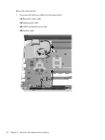
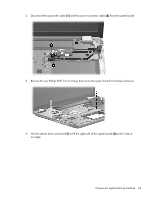
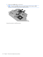
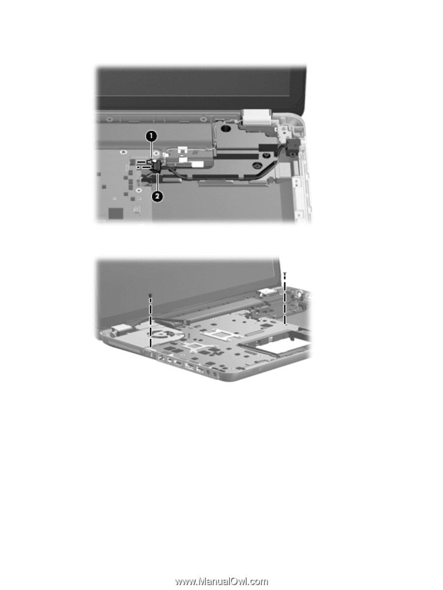
2. Disconnect the subwoofer cable (1) and the power connector cable (2) from the system board. 3. Remove the two Phillips PM2.5×5.0 screws that secure the system board to the base enclosure. 4. Use the optical drive connector (1) to lift the right side of the system board (2) until it rests at an angle. Component replacement procedures 63
-
 1
1 -
2
-
3
-
4
-
5
-
6
-
7
-
8
-
9
-
10
-
11
-
12
-
13
-
14
-
15
-
16
-
17
-
18
-
19
-
20
-
21
-
22
-
23
-
24
-
25
-
26
-
27
-
28
-
29
-
30
-
31
-
32
-
33
-
34
-
35
-
36
-
37
-
38
-
39
-
40
-
41
-
42
-
43
-
44
-
45
-
46
-
47
-
48
-
49
-
50
-
51
-
52
-
53
-
54
-
55
-
56
-
57
-
58
-
59
-
60
-
61
-
62
-
63
-
64
-
65
-
66
-
67
-
 68
68 -
 69
69 -
 70
70 -
 71
71 -
 72
72 -
 73
73 -
 74
74 -
 75
75 -
 76
76 -
 77
77 -
 78
78 -
79
-
80
-
81
-
82
-
83
-
84
-
85
-
86
-
87
-
88
-
89
-
90
-
91
-
92
-
93
-
94
-
95
-
96
-
97
-
98
-
99
-
100
-
101
-
102
-
103
-
104
-
105
-
106
-
107
-
108
-
109
-
110
-
111
-
112
-
113
-
114
-
115
-
116
-
117
-
118
-
119
-
120
 |
 |
2.
Disconnect the subwoofer cable
(1)
and the power connector cable
(2)
from the system board.
3.
Remove the two Phillips PM2.5×5.0 screws that secure the system board to the base enclosure.
4.
Use the optical drive connector
(1)
to lift the right side of the system board
(2)
until it rests at
an angle.
Component replacement procedures
63