HP ENVY TouchSmart m6-k000 HP ENVY Sleekbook and HP ENVY Touchsmart - Maintena - Page 48
System board, Remove the fan see
 |
View all HP ENVY TouchSmart m6-k000 manuals
Add to My Manuals
Save this manual to your list of manuals |
Page 48 highlights
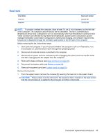
System board NOTE: The system board spare part kit includes replacement thermal material. Description Spare part number A76M A-10-5745M for use with computer models equipped with graphics subsystem with 725462-001 UMA memory A76M A-10-5745M for use with computer models equipped with graphics subsystem with 725462-501 UMA memory and the Windows 8 Standard operating system A76M A8-5545M for use with computer models equipped with graphics subsystem with UMA memory 725463-001 A76M A8-5545M for use with computer models equipped with graphics subsystem with UMA memory and the Windows 8 Standard operating system 725463-501 For use with computer models equipped with Intel i7-4500U processor and graphics subsystem with UMA memory 732774-001 For use with computer models equipped with Intel i7-4500U processor, graphics subsystem with UMA memory, and the Windows 8 Standard operating system 732774-501 For use with computer models equipped with Intel i7-4500U processor, graphics subsystem with UMA memory, and the Windows 8 Professional operating system 732774-601 For use with computer models equipped with Intel i5-4200U processor and graphics subsystem with UMA memory 732775-001 For use with computer models equipped with Intel i5-4200U processor, graphics subsystem with UMA memory, and the Windows 8 Standard operating system 732775-501 For use with computer models equipped with Intel i5-4200U processor, graphics subsystem with UMA memory, and the Windows 8 Professional operating system 732775-601 Before removing the system board, follow these steps: 1. Shut down the computer. If you are unsure whether the computer is off or in Hibernation, turn the computer on, and then shut it down through the operating system. 2. Disconnect all external devices connected to the computer. 3. Disconnect the power from the computer by first unplugging the power cord from the AC outlet and then unplugging the AC adapter from the computer. 4. Remove the base enclosure (see Base enclosure on page 27). 5. Remove the battery (see Battery on page 29). 6. Remove the WLAN module (see WLAN module). 7. Remove the fan (see Fan on page 36). When replacing the system board, be sure that the following components are removed from the defective system board and installed on the replacement system board: ● RTC battery (see RTC battery on page 30) ● Power connector cable (see Power connector cable on page 48) ● Fan (see Fan on page 36). ● Heat sink (see Heat sink on page 43) 40 Chapter 4 Removal and replacement procedures
-
 1
1 -
2
-
3
-
4
-
5
-
6
-
7
-
8
-
9
-
10
-
11
-
12
-
13
-
14
-
15
-
16
-
17
-
18
-
19
-
20
-
21
-
22
-
23
-
24
-
25
-
26
-
27
-
28
-
29
-
30
-
31
-
32
-
33
-
34
-
35
-
36
-
37
-
38
-
39
-
40
-
41
-
42
-
 43
43 -
 44
44 -
 45
45 -
 46
46 -
 47
47 -
 48
48 -
 49
49 -
 50
50 -
 51
51 -
 52
52 -
 53
53 -
54
-
55
-
56
-
57
-
58
-
59
-
60
-
61
-
62
-
63
-
64
-
65
-
66
-
67
-
68
-
69
-
70
-
71
-
72
-
73
-
74
-
75
-
76
-
77
-
78
-
79
-
80
-
81
-
82
-
83
-
84
-
85
 |
 |
