HP ENVY TouchSmart m6-k025dx HP ENVY m6 Sleekbook HP ENVY Touchsmart m6 SleekB - Page 58
Heat sink, Remove the fan see
 |
View all HP ENVY TouchSmart m6-k025dx manuals
Add to My Manuals
Save this manual to your list of manuals |
Page 58 highlights
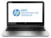
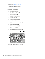
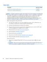
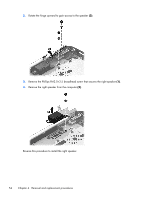
Heat sink Description Heat sink for use in models with AMD processors Heat sink for use in models with Intel processors Spare part number 725446-001 728132-001 NOTE: To properly ventilate the computer, allow at least 7.6 cm (3 in) of clearance on the left side of the computer. The computer uses an electric fan for ventilation. The fan is controlled by a temperature sensor and is designed to turn on automatically when high temperature conditions exist. These conditions are affected by high external temperatures, system power consumption, power management/battery conservation configurations, battery fast charging, and software requirements. Exhaust air is displaced through the ventilation grill located on the left side of the computer. Before removing the fan, follow these steps: 1. Shut down the computer. If you are unsure whether the computer is off or in Hibernation, turn the computer on, and then shut it down through the operating system. 2. Disconnect all external devices connected to the computer. 3. Disconnect the power from the computer by first unplugging the power cord from the AC outlet and then unplugging the AC adapter from the computer. 4. Remove the service cover (see Service cover on page 30). 5. Remove the battery (see Battery on page 32). 6. Remove the fan (see Fan on page 45). 7. Remove the card reader board (see Card reader board on page 44). 8. Remove the system board (see System board on page 47). Remove the heat sink: 1. Remove the 4 broadhead Phillips PM2.5×2.5 screws securing the heat sink (1) to the system board. CAUTION: These screws must be removed in the sequence that is marked on the heat sink so that the correct pressure is applied to the processor and other components. 50 Chapter 4 Removal and replacement procedures
-
 1
1 -
2
-
3
-
4
-
5
-
6
-
7
-
8
-
9
-
10
-
11
-
12
-
13
-
14
-
15
-
16
-
17
-
18
-
19
-
20
-
21
-
22
-
23
-
24
-
25
-
26
-
27
-
28
-
29
-
30
-
31
-
32
-
33
-
34
-
35
-
36
-
37
-
38
-
39
-
40
-
41
-
42
-
43
-
44
-
45
-
46
-
47
-
48
-
49
-
50
-
51
-
52
-
 53
53 -
 54
54 -
 55
55 -
 56
56 -
 57
57 -
 58
58 -
 59
59 -
 60
60 -
 61
61 -
 62
62 -
 63
63 -
64
-
65
-
66
-
67
-
68
-
69
-
70
-
71
-
72
-
73
-
74
-
75
-
76
-
77
-
78
-
79
-
80
-
81
-
82
-
83
-
84
-
85
-
86
-
87
-
88
-
89
-
90
-
91
-
92
-
93
-
94
-
95
-
96
 |
 |