HP ENVY m6-n168ca HP ENVY m6 Notebook PC HP ENVY Notebook PC Maintenance and S - Page 55
Removal and replacement procedures for Authorized Service Provider parts, Component replacement
 |
View all HP ENVY m6-n168ca manuals
Add to My Manuals
Save this manual to your list of manuals |
Page 55 highlights
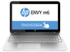
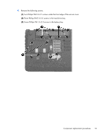
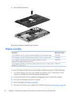
6 Removal and replacement procedures for Authorized Service Provider parts CAUTION: Components described in this chapter should only be accessed by an authorized service provider. Accessing these parts can damage the computer or void the warranty. NOTE: HP continually improves and changes product parts. For complete and current information on supported parts for your computer, go to http://partsurfer.hp.com, select your country or region, and then follow the on-screen instructions. Component replacement procedures This chapter provides removal and replacement procedures for Authorized Service Provider only parts. There are as many as 94 screws that must be removed, replaced, and/or loosened when servicing the computer. Make special note of each screw size and location during removal and replacement. RTC battery Description For use only on computer models equipped with an AMD processor For use only on computer models equipped with an Intel processor Spare part number 651948-001 718440-001 Before removing the RTC battery, follow these steps: 1. Turn off the computer. If you are unsure whether the computer is off or in Hibernation, turn the computer on, and then shut it down through the operating system. 2. Disconnect the power from the computer by unplugging the power cord from the computer. 3. Disconnect all external devices from the computer. 4. Remove the battery (see Battery on page 38). 5. Remove the service cover (see WLAN module on page 39). Component replacement procedures 47
-
 1
1 -
2
-
3
-
4
-
5
-
6
-
7
-
8
-
9
-
10
-
11
-
12
-
13
-
14
-
15
-
16
-
17
-
18
-
19
-
20
-
21
-
22
-
23
-
24
-
25
-
26
-
27
-
28
-
29
-
30
-
31
-
32
-
33
-
34
-
35
-
36
-
37
-
38
-
39
-
40
-
41
-
42
-
43
-
44
-
45
-
46
-
47
-
48
-
49
-
 50
50 -
 51
51 -
 52
52 -
 53
53 -
 54
54 -
 55
55 -
 56
56 -
 57
57 -
 58
58 -
 59
59 -
 60
60 -
61
-
62
-
63
-
64
-
65
-
66
-
67
-
68
-
69
-
70
-
71
-
72
-
73
-
74
-
75
-
76
-
77
-
78
-
79
-
80
-
81
-
82
-
83
-
84
-
85
-
86
-
87
-
88
-
89
-
90
-
91
-
92
-
93
-
94
-
95
-
96
-
97
-
98
-
99
-
100
-
101
-
102
-
103
-
104
-
105
-
106
 |
 |