HP ENVY x2 - 13t-j000 HP ENVY x2 (model numbers 13- j000 through 13-j099) Main - Page 28
Removal and replacement procedures, Component replacement procedures, Back cover
 |
View all HP ENVY x2 - 13t-j000 manuals
Add to My Manuals
Save this manual to your list of manuals |
Page 28 highlights
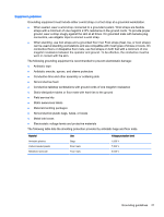
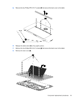
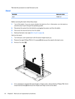
5 Removal and replacement procedures CAUTION: Components described in this chapter should only be accessed by an authorized service provider. Accessing these parts can damage the tablet or void the warranty. NOTE: HP continually improves and changes product parts. For complete and current information on supported parts for your tablet, go to http://partsurfer.hp.com, select your country or region, and then follow the on-screen instructions. Component replacement procedures There are as many as 46 screws that must be removed, replaced, and/or loosened when servicing the tablet. Make special note of each screw size and location during removal and replacement. Back cover Description Back cover Spare part number 787259-001 Before disassembling the tablet, follow these steps: 1. Turn off the tablet. If you are unsure whether the tablet is off or in Hibernation, turn the tablet on, and then shut it down through the operating system. 2. Disconnect the power from the tablet by unplugging the power cord from the tablet. 3. Disconnect all external devices from the tablet. NOTE: When replacing the back cover, be sure that the stand (see Stand on page 24) is removed from the defective back cover and installed on the replacement back cover. CAUTION: Before positioning the tablet with the display panel facing down, make sure the work surface is clear of tools, screws, and any other foreign objects. Failure to follow this caution can result in damage to the display panel assembly. Remove the back cover: 1. Position the tablet with the display panel facing down and the and the tablet bottom edge toward you. 2. Remove the recess cover (1). The recess cover is available using spare part number 787263-001. 3. Remove the four Phillips PM1.9×3.7 screws (2) that secure the back cover to the tablet. 4. Remove the two screw covers (3) from the bottom edge of the tablet. 22 Chapter 5 Removal and replacement procedures
-
 1
1 -
2
-
3
-
4
-
5
-
6
-
7
-
8
-
9
-
10
-
11
-
12
-
13
-
14
-
15
-
16
-
17
-
18
-
19
-
20
-
21
-
22
-
 23
23 -
 24
24 -
 25
25 -
 26
26 -
 27
27 -
 28
28 -
 29
29 -
 30
30 -
 31
31 -
 32
32 -
 33
33 -
34
-
35
-
36
-
37
-
38
-
39
-
40
-
41
-
42
-
43
-
44
-
45
-
46
-
47
-
48
-
49
-
50
-
51
-
52
-
53
-
54
-
55
-
56
-
57
-
58
-
59
 |
 |