HP Elite 7500 Maintenance & Service Guide HP Elite 7300 & 7500 Microto - Page 135
while routing
 |
View all HP Elite 7500 manuals
Add to My Manuals
Save this manual to your list of manuals |
Page 135 highlights
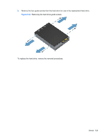
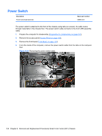
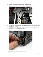
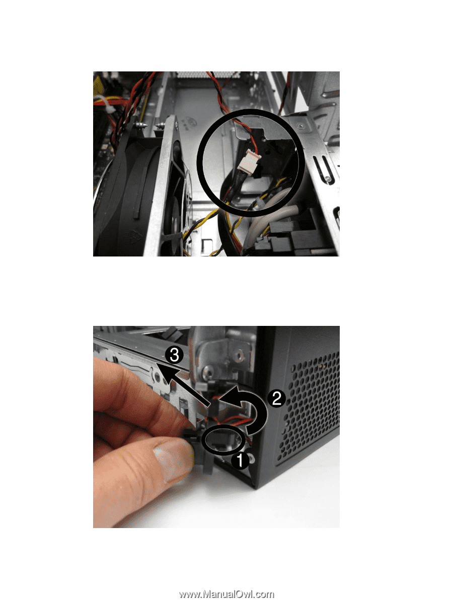
5. Disconnect the power switch cable from the front USB assembly cable. Figure 8-25 Disconnecting the power switch cable 6. From the outside, front of the computer, press the tab on the right side of the power switch (1) to disengage it from the chassis. 7. Rotate the power switch right to left (2), and then remove it from the computer (3) while routing the cable through the hole in the front of the chassis. Figure 8-26 Removing the power switch To install the power switch, reverse the removal procedure. Power Switch 125
-
 1
1 -
2
-
3
-
4
-
5
-
6
-
7
-
8
-
9
-
10
-
11
-
12
-
13
-
14
-
15
-
16
-
17
-
18
-
19
-
20
-
21
-
22
-
23
-
24
-
25
-
26
-
27
-
28
-
29
-
30
-
31
-
32
-
33
-
34
-
35
-
36
-
37
-
38
-
39
-
40
-
41
-
42
-
43
-
44
-
45
-
46
-
47
-
48
-
49
-
50
-
51
-
52
-
53
-
54
-
55
-
56
-
57
-
58
-
59
-
60
-
61
-
62
-
63
-
64
-
65
-
66
-
67
-
68
-
69
-
70
-
71
-
72
-
73
-
74
-
75
-
76
-
77
-
78
-
79
-
80
-
81
-
82
-
83
-
84
-
85
-
86
-
87
-
88
-
89
-
90
-
91
-
92
-
93
-
94
-
95
-
96
-
97
-
98
-
99
-
100
-
101
-
102
-
103
-
104
-
105
-
106
-
107
-
108
-
109
-
110
-
111
-
112
-
113
-
114
-
115
-
116
-
117
-
118
-
119
-
120
-
121
-
122
-
123
-
124
-
125
-
126
-
127
-
128
-
129
-
 130
130 -
 131
131 -
 132
132 -
 133
133 -
 134
134 -
 135
135 -
 136
136 -
 137
137 -
 138
138 -
 139
139 -
 140
140 -
141
-
142
-
143
-
144
-
145
-
146
-
147
-
148
-
149
-
150
-
151
-
152
-
153
-
154
-
155
-
156
-
157
-
158
-
159
-
160
-
161
-
162
-
163
-
164
-
165
-
166
-
167
-
168
-
169
-
170
-
171
-
172
-
173
-
174
-
175
-
176
-
177
-
178
-
179
-
180
-
181
-
182
-
183
-
184
-
185
-
186
-
187
-
188
-
189
-
190
-
191
-
192
-
193
-
194
-
195
-
196
-
197
-
198
-
199
-
200
-
201
-
202
-
203
-
204
-
205
-
206
-
207
-
208
-
209
-
210
-
211
-
212
-
213
-
214
-
215
-
216
-
217
-
218
-
219
-
220
-
221
-
222
-
223
-
224
-
225
-
226
-
227
-
228
-
229
-
230
 |
 |
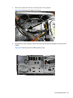
5.
Disconnect the power switch cable from the front USB assembly cable.
Figure 8-25
Disconnecting the power switch cable
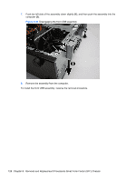
6.
From the outside, front of the computer, press the tab on the right side of the power switch
(1)
to
disengage it from the chassis.
7.
Rotate the power switch right to left
(2)
, and then remove it from the computer
(3)
while routing
the cable through the hole in the front of the chassis.
Figure 8-26
Removing the power switch
To install the power switch, reverse the removal procedure.
Power Switch
125