HP FH554AT HP 530 Notebook PC - Maintenance and Service Guide - Page 44
Memory modules are designed with a notch, Remove the memory module
 |
UPC - 884420136132
View all HP FH554AT manuals
Add to My Manuals
Save this manual to your list of manuals |
Page 44 highlights
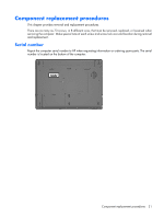
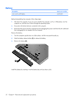
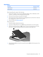
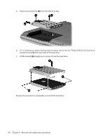
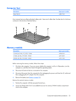
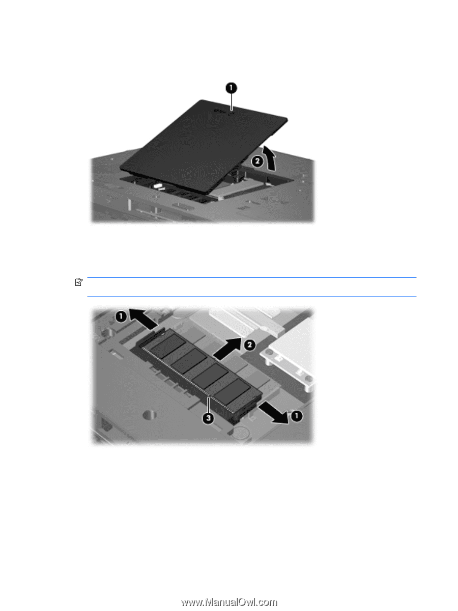
3. Lift the front edge of the cover (2), swing it toward you, and remove the cover. The memory/WLAN module compartment cover is included in the Plastics/Hardware Kit, spare part number 448431-001. 4. Spread the retaining tabs (1) on each side of the memory module slot to release the memory module. (The edge of the module opposite the slot rises away from the computer.) 5. Remove the memory module (2) by pulling the module away from the slot at an angle. NOTE: Memory modules are designed with a notch (3) to prevent incorrect installation into the memory module slot. Reverse this procedure to install a memory module. 36 Chapter 4 Removal and replacement procedures
-
 1
1 -
2
-
3
-
4
-
5
-
6
-
7
-
8
-
9
-
10
-
11
-
12
-
13
-
14
-
15
-
16
-
17
-
18
-
19
-
20
-
21
-
22
-
23
-
24
-
25
-
26
-
27
-
28
-
29
-
30
-
31
-
32
-
33
-
34
-
35
-
36
-
37
-
38
-
 39
39 -
 40
40 -
 41
41 -
 42
42 -
 43
43 -
 44
44 -
 45
45 -
 46
46 -
 47
47 -
 48
48 -
 49
49 -
50
-
51
-
52
-
53
-
54
-
55
-
56
-
57
-
58
-
59
-
60
-
61
-
62
-
63
-
64
-
65
-
66
-
67
-
68
-
69
-
70
-
71
-
72
-
73
-
74
-
75
-
76
-
77
-
78
-
79
-
80
-
81
-
82
-
83
-
84
-
85
-
86
-
87
-
88
-
89
-
90
-
91
-
92
-
93
-
94
-
95
-
96
-
97
-
98
-
99
-
100
-
101
-
102
-
103
-
104
-
105
-
106
-
107
-
108
-
109
-
110
-
111
-
112
-
113
-
114
-
115
-
116
-
117
-
118
-
119
-
120
-
121
-
122
-
123
-
124
-
125
-
126
-
127
-
128
-
129
-
130
-
131
-
132
-
133
-
134
-
135
-
136
-
137
-
138
 |
 |
3
.
Lift the front edge of the cover
(2)
, swing it toward you, and remove the cover. The memory/WLAN
module compartment cover is included in the Plastics/Hardware Kit, spare part number
448431-001.
4
.
Spread the retaining tabs
(1)
on each side of the memory module slot to release the memory module.
(The edge of the module opposite the slot rises away from the computer.)
5
.
Remove the memory module
(2)
by pulling the module away from the slot at an angle.
NOTE:
Memory modules are designed with a notch
(3)
to prevent incorrect installation into the
memory module slot.
Reverse this procedure to install a memory module.
36
Chapter
4
Removal and replacement procedures