HP G42-100 Compaq Presario CQ42 Notebook PC and HP G42 Notebook PC - Maintenan - Page 91
Fan/heat sink assembly, Remove the following components
 |
View all HP G42-100 manuals
Add to My Manuals
Save this manual to your list of manuals |
Page 91 highlights
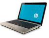
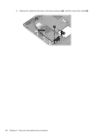
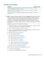
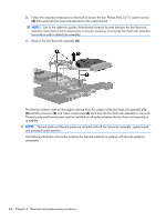
Fan/heat sink assembly Description Fan/heat sink assembly for use in models that use Universal Memory Architecture (UMA) graphics subsystem memory (includes thermal replacement material) Fan/heat sink assembly for use in models that use and UMA graphics subsystem memory and the Intel® GL40 chipset (includes thermal material) Fan/heat sink assembly for use in models that use discrete graphics subsystem memory (includes thermal material) Spare part number 595832-001 606573-001 606573-001 NOTE: To properly ventilate the computer, allow at least a 7.6-cm (3-inch) clearance on the right side and rear panel of the computer. The computer uses an electric fan for ventilation. The fan is controlled by a temperature sensor and is designed to turn on automatically when high temperature conditions exist. These conditions are affected by high external temperatures, system power consumption, power management/battery conservation configurations, battery fast charging, and software requirements. Exhaust air is displaced through the ventilation grill located on the left side of the computer. Before removing the fan/heat sink assembly, follow these steps: 1. Shut down the computer. If you are unsure whether the computer is off or in Hibernation, turn the computer on, and then shut it down through the operating system. 2. Disconnect all external devices connected to the computer. 3. Disconnect the power from the computer by first unplugging the power cord from the AC outlet and then unplugging the AC adapter from the computer. 4. Remove the battery (see Battery on page 41). 5. Remove the following components: a. Hard drive (see Hard drive on page 42) b. Optical drive (see Optical drive on page 45) c. Keyboard (see Keyboard on page 52) d. Top cover (see Top cover on page 54) e. Speaker assembly (see Speaker assembly on page 57) f. Display assembly (see Display assembly on page 69) g. System board (see System board on page 76) Remove the fan/heat assembly (fan/heat sink appearance may vary): 1. Turn the system board upside down. 2. Disconnect the fan cable (1) from the system board. Component replacement procedures 83
-
 1
1 -
2
-
3
-
4
-
5
-
6
-
7
-
8
-
9
-
10
-
11
-
12
-
13
-
14
-
15
-
16
-
17
-
18
-
19
-
20
-
21
-
22
-
23
-
24
-
25
-
26
-
27
-
28
-
29
-
30
-
31
-
32
-
33
-
34
-
35
-
36
-
37
-
38
-
39
-
40
-
41
-
42
-
43
-
44
-
45
-
46
-
47
-
48
-
49
-
50
-
51
-
52
-
53
-
54
-
55
-
56
-
57
-
58
-
59
-
60
-
61
-
62
-
63
-
64
-
65
-
66
-
67
-
68
-
69
-
70
-
71
-
72
-
73
-
74
-
75
-
76
-
77
-
78
-
79
-
80
-
81
-
82
-
83
-
84
-
85
-
 86
86 -
 87
87 -
 88
88 -
 89
89 -
 90
90 -
 91
91 -
 92
92 -
 93
93 -
 94
94 -
 95
95 -
 96
96 -
97
-
98
-
99
-
100
-
101
-
102
-
103
-
104
-
105
-
106
-
107
-
108
-
109
-
110
-
111
-
112
-
113
-
114
-
115
-
116
-
117
-
118
-
119
-
120
-
121
-
122
-
123
-
124
-
125
-
126
-
127
-
128
-
129
-
130
-
131
-
132
-
133
-
134
-
135
-
136
-
137
-
138
 |
 |