HP G60-233CA Service Guide - Page 79
System board, Optical drive see
 |
View all HP G60-233CA manuals
Add to My Manuals
Save this manual to your list of manuals |
Page 79 highlights
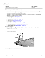
System board ✎ The system board spare part kit includes UMA or discrete graphics subsystem memory, built-in modem, and replacement thermal material. Description Spare part number UMA system board, GM45 (includes built-in modem, Digital Media Slot, HDMI port, and replacement thermal material) 485218-001 UMA system board, GM45 (includes built-in modem, Digital Media Slot, and replacement thermal material) 494281-001 UMA system board, GL40 (includes built-in modem, Digital Media Slot, and replacement thermal material) 494282-001 UMA system board, GL40 (includes built-in modem, Digital Media Slot, HDMI port, and 485219-001 replacement thermal material) UMA system board, GL40 (for Presario CQ60 only; includes built-in modem, and replacement thermal material) 501266-001 Discrete system board, PM45 (includes built-in modem, Digital Media Slot, HDMI port, 488338-001 and replacement thermal material) Discrete system board, PM45 (includes built-in modem, Digital Media Slot, and replacement thermal material) 494283-001 UMA system board, NVIDIA (includes built-in modem, Digital Media Slot, HDMI port, 498460-001 and replacement thermal material) UMA system board, NVIDIA (for Presario only; includes built-in modem, Digital Media 498462-001 Slot, and replacement thermal material) UMA system board, NVIDIA (for Presario only; includes built-in modem, Digital Media 498463-001 Slot, and replacement thermal material) UMA system board, NVIDIA (for Presario only; includes built-in modem, and replacement thermal material) 498464-001 Optical extension board (not illustrated) 506951-001 Before removing the system board, follow these steps: 1. Shut down the computer. If you are unsure whether the computer is off or in Hibernation, turn the computer on, and then shut it down through the operating system. 2. Disconnect all external devices connected to the computer. 3. Disconnect the power from the computer by first unplugging the power cord from the AC outlet and then unplugging the AC adapter from the computer. 4. Remove the battery (see "Battery" on page 4-7). 5. Remove the following components: a. Optical drive (see "Optical drive" on page 4-8) b. Hard drive (see "Hard drive" on page 4-10) c. Keyboard (see "Keyboard" on page 4-17) d. Keyboard cover (see "Keyboard cover" on page 4-20) e. Power button board (see "Power button board" on page 4-22) f. Display assembly (see "Display assembly" on page 4-23) Removal and replacement procedures 4-38
-
 1
1 -
2
-
3
-
4
-
5
-
6
-
7
-
8
-
9
-
10
-
11
-
12
-
13
-
14
-
15
-
16
-
17
-
18
-
19
-
20
-
21
-
22
-
23
-
24
-
25
-
26
-
27
-
28
-
29
-
30
-
31
-
32
-
33
-
34
-
35
-
36
-
37
-
38
-
39
-
40
-
41
-
42
-
43
-
44
-
45
-
46
-
47
-
48
-
49
-
50
-
51
-
52
-
53
-
54
-
55
-
56
-
57
-
58
-
59
-
60
-
61
-
62
-
63
-
64
-
65
-
66
-
67
-
68
-
69
-
70
-
71
-
72
-
73
-
 74
74 -
 75
75 -
 76
76 -
 77
77 -
 78
78 -
 79
79 -
 80
80 -
 81
81 -
 82
82 -
 83
83 -
 84
84 -
85
-
86
-
87
-
88
-
89
-
90
-
91
-
92
-
93
-
94
-
95
-
96
-
97
-
98
-
99
-
100
-
101
-
102
-
103
-
104
-
105
-
106
-
107
-
108
-
109
-
110
-
111
-
112
-
113
-
114
-
115
-
116
-
117
-
118
-
119
-
120
-
121
-
122
-
123
-
124
-
125
-
126
-
127
-
128
-
129
-
130
-
131
-
132
-
133
-
134
-
135
-
136
-
137
-
138
 |
 |