HP Indigo WS6000 Electrometer Board Test - Page 13
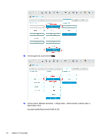
Element Activation > Charge Roller, If needed, adjust gauge at 'P2' using small flat screwdriver.
 |
View all HP Indigo WS6000 manuals
Add to My Manuals
Save this manual to your list of manuals |
Page 13 highlights
15. From the press UI: Element Activation > Charge Roller, activate the charge roller voltage. 16. Check the 'Charge roller voltage' value as follows: ■ Use a DC Voltmeter (Fluke) to verify 24V in pins 3 and 1 of the electrometer board Molex connector CP2 and then, 10V in pins 2 and 4 of connector CP2. (Accepted results): same as 'Charge roller voltage' value/10 ±0.10 VDC (example: 1000VDC at the UI will read 10.0 VDC ±0.10 VDC). NOTE: If needed, adjust gauge at 'P2' using small flat screwdriver. Board test procedure 11
-
 1
1 -
2
-
3
-
4
-
5
-
6
-
7
-
 8
8 -
 9
9 -
 10
10 -
 11
11 -
 12
12 -
 13
13 -
 14
14 -
 15
15 -
 16
16 -
 17
17 -
 18
18 -
19
-
20
-
21
-
22
-
23
-
24
-
25
-
26
-
27
-
28
-
29
-
30
-
31
 |
 |

15.
From the press UI:
Element Activation > Charge Roller
, activate the charge roller voltage.
16.
Check the ‘Charge roller voltage’ value as follows:
■
Use a DC Voltmeter (Fluke) to verify 24V in pins 3 and 1 of the electrometer board Molex connector
CP2 and then, 10V in pins 2 and 4 of connector CP2.
(Accepted results): same as ‘Charge roller voltage’ value/10 ±0.10 VDC (example: 1000VDC at the UI
will read 10.0 VDC ±0.10 VDC).
NOTE:
If needed, adjust gauge at ‘P2’ using small flat screwdriver.
Board test procedure
11