HP Integrity rx7640 Site Preparation Guide, Fourth Edition - HP Integrity rx76
HP Integrity rx7640 Manual
 |
View all HP Integrity rx7640 manuals
Add to My Manuals
Save this manual to your list of manuals |
HP Integrity rx7640 manual content summary:
- HP Integrity rx7640 | Site Preparation Guide, Fourth Edition - HP Integrity rx76 - Page 1
HP Integrity rx7640 and HP 9000 rp7440 Servers Site Preparation Guide HP Part Number: AB312-9011A Published: November 2007 Edition: 4 - HP Integrity rx7640 | Site Preparation Guide, Fourth Edition - HP Integrity rx76 - Page 2
to change without notice. The only warranties for HP products and services are set forth in the express warranty statements accompanying such products and services. Nothing herein should be construed as constituting an additional warranty. HP shall not be liable for technical or editorial errors - HP Integrity rx7640 | Site Preparation Guide, Fourth Edition - HP Integrity rx76 - Page 3
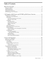
1 HP Integrity rx7640 Server and HP 9000 rp7440 Server Overview 13 Detailed Server Description...13 Dimensions and Components...14 Front Panel...17 Front Panel Indicators and Controls 17 Enclosure Status LEDs...17 Cell Board...18 PDH Riser Board...19 Central Processor Units...19 Memory Subsystem - HP Integrity rx7640 | Site Preparation Guide, Fourth Edition - HP Integrity rx76 - Page 4
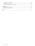
Acoustic Noise Specification...34 Airflow...34 System Requirements Summary...35 Power Consumption and Air Conditioning 35 A Templates...37 Equipment Footprint Templates...37 Computer Room Layout Plan...37 Index...41 4 Table of Contents - HP Integrity rx7640 | Site Preparation Guide, Fourth Edition - HP Integrity rx76 - Page 5
LEDs and Power Switch 18 1-7 Cell Board...18 1-8 CPU Locations on Cell Board...20 1-9 Memory Subsystem...21 1-10 Disk Drive and DVD Drive Location 22 1-11 System Backplane Block Diagram 23 1-12 PCI-X Board to Cell Board Block Diagram 24 2-1 Airflow Diagram ...35 A-1 Server Space Requirements - HP Integrity rx7640 | Site Preparation Guide, Fourth Edition - HP Integrity rx76 - Page 6
6 - HP Integrity rx7640 | Site Preparation Guide, Fourth Edition - HP Integrity rx76 - Page 7
List of Tables 1-1 Cell Board CPU Module Load Order 19 1-2 Server DIMMs...21 1-3 PCI-X paths for Cell 0...24 1-4 PCI-X Paths Cell 1...25 1-5 PCI-X Slot Types...26 1-6 PCI-X/PCIe Slot Types...27 2-1 Server Dimensions and Weights 29 2-2 Server Component Weights...29 2-3 Example Weight Summary...29 - HP Integrity rx7640 | Site Preparation Guide, Fourth Edition - HP Integrity rx76 - Page 8
8 - HP Integrity rx7640 | Site Preparation Guide, Fourth Edition - HP Integrity rx76 - Page 9
concerning those topics, refer to the HP System Partitions Guide: Administration for nPartitions. Intended Audience This document is intended to be used by customer engineers assigned to support the HP Integrity rx7640 and HP 9000 rp7440 Servers. Publishing History The Printing History below - HP Integrity rx7640 | Site Preparation Guide, Fourth Edition - HP Integrity rx76 - Page 10
management, Microsoft® Windows® administration, and diagnostic support tools at the following Web sites: http://docs.hp.com The main Web site for HP technical documentation is http://docs.hp.com. Server Hardware Information: http://docs.hp.com/hpux/hw/ The http://docs.hp.com/hpux/hw/ Web site is the - HP Integrity rx7640 | Site Preparation Guide, Fourth Edition - HP Integrity rx76 - Page 11
, recommendations, or important details about HP product features. • Commands and options are represented using this font. • Text that you type exactly as shown is represented using this font. • Text to be replaced with text that you supply is represented using this font. Example: "Enter the - HP Integrity rx7640 | Site Preparation Guide, Fourth Edition - HP Integrity rx76 - Page 12
providing documentation that meets your needs. Send any errors found, suggestions for improvement, or compliments to: [email protected] Include the document title, manufacturing part number, and any comment, error found, or suggestion for improvement you have concerning this document. 12 About This - HP Integrity rx7640 | Site Preparation Guide, Fourth Edition - HP Integrity rx76 - Page 13
HP 9000 rp7440 Server only. IMPORTANT: Ensure a valid UUID is either in place or available prior to maintenance of these servers. This step is vital when performing upgrades and is recommended for existing hardware service restoration. Specific information for upgrades is found in the Upgrade Guide - HP Integrity rx7640 | Site Preparation Guide, Fourth Edition - HP Integrity rx76 - Page 14
Figure 1-1 8-Socket Server Block Diagram Cell Board 0 Memory Cell Board 0 Memory PDH CPU CPU CC CPU CPU CPU CPU CC CPU CPU CC Link Bulk Power Supply (x2) Clocks Reset System Backplane PCI-X Power (x2) Indicates hot pluggable link or bus Indicates cable SBA Link SBA LBA LBA LBA LBA - HP Integrity rx7640 | Site Preparation Guide, Fourth Edition - HP Integrity rx76 - Page 15
Figure 1-2 Server (Front View With Bezel) Figure 1-3 Server (Front View Without Bezel) Power Switch Removable Media Drive PCI Power Supplies Front OLR Fans Bulk Power Supplies Hard Disk Drives Detailed Server Description 15 - HP Integrity rx7640 | Site Preparation Guide, Fourth Edition - HP Integrity rx76 - Page 16
Front Panel Display Board PCI Power Supplies Cell Boards B Bulk Power Supplies Access the PCI-X card section, located toward the rear, by removing the top cover. The PCI card bulkhead connectors are located at the rear top. 16 HP Integrity rx7640 Server and HP 9000 rp7440 Server Overview - HP Integrity rx7640 | Site Preparation Guide, Fourth Edition - HP Integrity rx76 - Page 17
mounted on the rear surface. The cell boards are accessed from the right side of the chassis behind a removable side cover. The two MP/SCSI boards are positioned vertically at the rear of the chassis. The two hot-pluggable N+1 redundant bulk power supplies provide a wide input voltage range. They - HP Integrity rx7640 | Site Preparation Guide, Fourth Edition - HP Integrity rx76 - Page 18
Front Panel LEDs and Power Switch Cell Board The cell board, illustrated in Figure 1-7, contains the processors, main memory, and the CC application specific integrated circuit (ASIC) which interfaces the processors and memory with the I/O, and to the other cell board in the server. The CC is the - HP Integrity rx7640 | Site Preparation Guide, Fourth Edition - HP Integrity rx76 - Page 19
1-8 for the locations on the cell board for installing processor modules. NOTE: Unlike previous HP cell based systems, the HP Integrity rx7640 server cell board does not require that a termination module be installed at the end of an unused FSB. System firmware is allowed to disable an unused - HP Integrity rx7640 | Site Preparation Guide, Fourth Edition - HP Integrity rx76 - Page 20
comprises four independent quadrants. Each quadrant has its own memory data bus connected from the cell controller to the two buffers for the memory quadrant. Each quadrant also has two memory control buses; one for each buffer. 20 HP Integrity rx7640 Server and HP 9000 rp7440 Server Overview - HP Integrity rx7640 | Site Preparation Guide, Fourth Edition - HP Integrity rx76 - Page 21
DIMM modules are not supported. The server supports DIMMs with densities of 1, 2, and 4 Gb. Table 1-2 (page 21) lists each supported DIMM size, the resulting total system capacity, and the memory component density. Each DIMM is connected to two buffer chips on the cell board. See Appendix C for more - HP Integrity rx7640 | Site Preparation Guide, Fourth Edition - HP Integrity rx76 - Page 22
, power supplies, and fans. A server complex can contain one or two nPartitions, enabling the hardware to function as a single system or as multiple systems. NOTE: Partition configuration information is available on the Web at: http://docs.hp.com Refer to HP System Partitions Guide: Administration - HP Integrity rx7640 | Site Preparation Guide, Fourth Edition - HP Integrity rx76 - Page 23
MP/SCSI MP Core I/O MP/SCSI System backplane PCI-X backplane Cell board 1 Cell board 0 Cell boards are perpendicular to the system backplane. Bulk power supply System Bacplane to PCI-X Backplane Connectivity The PCI-X backplane uses two connectors for the SBA link bus and two connectors for the - HP Integrity rx7640 | Site Preparation Guide, Fourth Edition - HP Integrity rx76 - Page 24
in cell slot 1. Table 1-3 PCI-X paths for Cell 0 Cell PCI-X Slot IO Chassis Path 0 1 0 0/0/8/1 0 2 0 0/0/10/1 0 3 0 0/0/12/1 0 4 0 0/0/14/1 0 5 0 0/0/6/1 0 6 0 0/0/4/1 0 7 0 0/0/2/1 0 8 0 0/0/1/1 24 HP Integrity rx7640 Server and HP 9000 rp7440 Server Overview - HP Integrity rx7640 | Site Preparation Guide, Fourth Edition - HP Integrity rx76 - Page 25
is physically one board, but it specific PCI card performance specifications. PCI, PCI-X mode 1, and PCI-X mode 2 cards are supported at different clock speeds. Select the appropriate PCI-X I/O slot for best performance. Table 1-5 lists the PCI-X slot types supported on the server. Detailed Server - HP Integrity rx7640 | Site Preparation Guide, Fourth Edition - HP Integrity rx76 - Page 26
® Itanium® processor 9100 Series cell controller ASIC on the host cell board via a high bandwidth logical connection known as the HSS link.When installed in the SEU chassis within a fully configured system, the ASIC on cell location 0 connects 26 HP Integrity rx7640 Server and HP 9000 rp7440 Server - HP Integrity rx7640 | Site Preparation Guide, Fourth Edition - HP Integrity rx76 - Page 27
cell board 3 through external link cables. Downstream, the ASIC spawns 16 logical 'ropes' that communicate with the core I/O bridge on the system backplane, PCI interface chips, and PCIe interface chips. Each PCI chip produces a single 64-bit PCI-X bus supporting support to support 6 to support 8 - HP Integrity rx7640 | Site Preparation Guide, Fourth Edition - HP Integrity rx76 - Page 28
the required board and another that can accommodate either a second LAN/SCSI board or any other supported add-in PCI-X card. The LAN/SCSI board is enables power to the internal removable media device to be programmatically cycled. 28 HP Integrity rx7640 Server and HP 9000 rp7440 Server Overview - HP Integrity rx7640 | Site Preparation Guide, Fourth Edition - HP Integrity rx76 - Page 29
.4 (9.25) 18.0 (8.2) each 1.0 (0.45) 5.0 (2.27) each 1.60 (0.73) each 2.20 (1.00) each Table 2-3 Example Weight Summary Component Cell board PCI card (varies - used sample value) Power supply (BPS) Quantity 2 4 2 Multiply 27.8 (12.16) 0.34 (0.153) 18 (8.2) Weight (kg) 107.20 (48.64) 1.36 (0.61 - HP Integrity rx7640 | Site Preparation Guide, Fourth Edition - HP Integrity rx76 - Page 30
weight Table 2-4 Weight Summary Component Cell Board PCI Card Power Supply (BPS) DVD Drive Hard Disk server can receive AC input from two different AC power sources. System AC Power Specifications Power Cords Table 2-5 lists the various power cables available for use with the server. Each power - HP Integrity rx7640 | Site Preparation Guide, Fourth Edition - HP Integrity rx76 - Page 31
The measured maximum worst case power consumption. This number represents the larges power consumption that HP engineers were able to produce for the server with any combination of hardware under laboratory conditions using aggressive software applications designed specifically to work the system at - HP Integrity rx7640 | Site Preparation Guide, Fourth Edition - HP Integrity rx76 - Page 32
load. This number can safely be used to compute thermal loads and power consumption for the system under all conditions. Environmental Specifications This section provides the environmental, power dissipation, noise emission, and airflow specifications for the server. Temperature and Humidity The - HP Integrity rx7640 | Site Preparation Guide, Fourth Edition - HP Integrity rx76 - Page 33
for the HP Integrity rx7640 server. Table 2-9 Typical Server Configurations for the HP Integrity rx7640 Server Cell Boards Qty 2 2 Memory Per PCI Cards DVDs Cell Board (assumes 10 watts each) GBytes Qty Qty 32 16 2 16 8 0 Hard Disk Core I/O Bulk Power Typical Drives Supplies Power Qty - HP Integrity rx7640 | Site Preparation Guide, Fourth Edition - HP Integrity rx76 - Page 34
Table 2-9 Typical Server Configurations for the HP Integrity rx7640 Server (continued) Cell Boards Qty 2 1 Memory Per PCI Cards DVDs Cell Board (assumes 10 watts each) GBytes Qty Qty 8 8 0 8 8 0 Hard Disk Core I/O Bulk Power Typical Drives Supplies Power Qty Qty Qty 2 2 2 1 1 - HP Integrity rx7640 | Site Preparation Guide, Fourth Edition - HP Integrity rx76 - Page 35
is required to support these devices. Maximum power is the sum of the worst case power consumption of every subsystem in the box and should be used to size worst case power consumption. Typical power consumption numbers are what HP engineers have measured when running power-intensive applications - HP Integrity rx7640 | Site Preparation Guide, Fourth Edition - HP Integrity rx76 - Page 36
36 - HP Integrity rx7640 | Site Preparation Guide, Fourth Edition - HP Integrity rx76 - Page 37
number of floor plan grid sheets to create a scaled version of the computer room floor plan. Figure A-1 illustrates the overall dimensions required for the server. Figure A-1 Server servicing. The service areas shown on the template drawings are lightly shaded. The equipment templates should be used - HP Integrity rx7640 | Site Preparation Guide, Fourth Edition - HP Integrity rx76 - Page 38
computer room doors, air-conditioning floor vents, utility outlets, and so on. NOTE: Attach a reduced copy of the completed floor plan to the site survey. HP installation specialists use this floor plan during equipment installation. Figure A-2 Server Cabinet Template 38 Templates - HP Integrity rx7640 | Site Preparation Guide, Fourth Edition - HP Integrity rx76 - Page 39
Figure A-3 Planning Grid Computer Room Layout Plan 39 - HP Integrity rx7640 | Site Preparation Guide, Fourth Edition - HP Integrity rx76 - Page 40
Figure A-4 Planning Grid 40 Templates - HP Integrity rx7640 | Site Preparation Guide, Fourth Edition - HP Integrity rx76 - Page 41
riser board, 19 power plugs, 13 requirement, 13 power cords, 30 power requirements component, 31 power supplies, 13 processor service, 13 processors, 13 S server front panel, 17 service processor, 13 Standby power LED, 17 status LEDs, 17 system backplane, 17, 23, 28, 29, 33 system specifications, 29
-
 1
1 -
 2
2 -
 3
3 -
 4
4 -
 5
5 -
 6
6 -
 7
7 -
8
-
9
-
10
-
11
-
12
-
13
-
14
-
15
-
16
-
17
-
18
-
19
-
20
-
21
-
22
-
23
-
24
-
25
-
26
-
27
-
28
-
29
-
30
-
31
-
32
-
33
-
34
-
35
-
36
-
37
-
38
-
39
-
40
-
41
 |
 |

HP Integrity rx7640 and HP 9000 rp7440
Servers
Site Preparation Guide
HP Part Number: AB312–9011A
Published: November 2007
Edition: 4