HP Kayak XA 05xx HP Kayak XA Series 05xx, Technical Information For Minitower - Page 8
System Board Switches, on a Minitower HP Kayak XA Workstation
 |
View all HP Kayak XA 05xx manuals
Add to My Manuals
Save this manual to your list of manuals |
Page 8 highlights
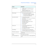
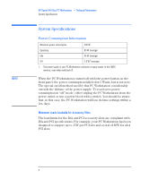
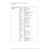
HP Kayak XA 05xx PC Workstation - Technical Information System Connectors and Switches System Board Switches The following diagram shows the position of the system board switches on a Minitower HP Kayak XA Workstation: System Board Switches Switch 1 is reserved and should not be used. Its default position is Up. Switches 2 through 5 are used for processor settings as shown in the following table and should be changed if the processor supplied with the PC Workstation is replaced with a faster one. Switch 2 Switch 3 Switch 4 Switch 5 Bus Speed UP1 UP DOWN DOWN 100 MHz UP DOWN UP UP 100 MHz UP DOWN UP DOWN 100 MHz UP DOWN DOWN UP 100 MHz 1. UP=OFF, DOWN=ON. Processor Speed 350 MHz 400 MHz 450 MHz 500 MHz 8 English
-
 1
1 -
2
-
 3
3 -
 4
4 -
 5
5 -
 6
6 -
 7
7 -
 8
8 -
 9
9
 |
 |

HP Kayak XA 05xx PC Workstation
— Technical Information
System Connectors and Switches
8
English
System Board Switches
The following diagram shows the position of the system board switches
on a Minitower HP Kayak XA Workstation:
Switch 1 is reserved and should not be used. Its default position is Up.
Switches 2 through 5 are used for processor settings as shown in the
following table and should be changed if the processor supplied with
the PC Workstation is replaced with a faster one.
System Board
Switches
Switch 2
Switch 3
Switch 4
Switch 5
Bus Speed
Processor Speed
UP
1
1.
UP=OFF, DOWN=ON.
UP
DOWN
DOWN
100 MHz
350 MHz
UP
DOWN
UP
UP
100 MHz
400 MHz
UP
DOWN
UP
DOWN
100 MHz
450 MHz
UP
DOWN
DOWN
UP
100 MHz
500 MHz