HP Kayak XW U3-W3 HP Kayak PC Workstations, HP MaxiLife Hardware Monitoring - Page 2
C bus, via the PCI/ISA chipset PIIX4E South - programs
 |
View all HP Kayak XW U3-W3 manuals
Add to My Manuals
Save this manual to your list of manuals |
Page 2 highlights
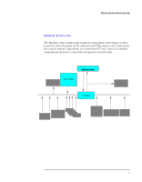
MaxiLife Hardware Monitoring Chip MaxiLife is a hardware monitoring chip which is resident on the system board. Its responsibility includes On/Off and reset control, status panel management (Lock button, LEDs), hardware monitoring (temperature and voltage), early diagnostics (CPU, DIMMs, PLLs, boot start), run-time diagnostics (CPU errors, package intrusions), and other miscellaneous functions (such as special OK/FAIL symbols based on a smiling face). The integrated microprocessor includes a Synopsys cell based on Dallas "8052" equivalent, a 2 KB boot ROM, 256 bytes of data RAM, an I2C cell, an Analog-to-Digital (ADC) with 5 entries, and an additional glue logic for interrupt control, fan regulation, and a status panel control. MaxiLife downloads its code in 96 milliseconds from an I2C serial EEPROM. The total firmware (MaxiLife 8051-code, running in RAM) size is 5 KB. As it exceeds the 2 KB program RAM space, a paging mechanism will swap code as it is required, based on a 512 byte buffer. The first 2 KB pages of firmware code is critical because it controls the initial power on/reset to boot the system. This initial page is checked with a null-checksum test and the presence of MaxiLife markers (located just below the 2 KB limit). If the boot block has been corrupted, the Firmware can start from its 'crisis' block. To do this, set the System board switch 10 to the Closed position. MaxiLife is partially replacing HP ASIC (Little Ben), and provides the necessary hardware monitoring control. However, MaxiLife is not accessible in I/O space or memory space of the system platform, but only through the SMBUS (which is a sub-set of the I2C bus), via the PCI/ISA chipset (PIIX4E South Bridge). Its I2C cell may operate either in Slave or Master mode, switched by firmware, or automatically in case of 'Arbitration' loss. As a monitoring chip, MaxiLife reports critical errors at start-up, and as such is powered by Vstandby (3.3V) power. For MaxiLife to work correctly, the PC Workstation must always be connected to a grounded outlet. This enables the PC Workstation's hardware monitoring chip to be active, even if the system has been powered off. 2
-
 1
1 -
 2
2 -
 3
3 -
 4
4 -
 5
5 -
 6
6 -
 7
7 -
 8
8 -
9
-
10
-
11
-
12
-
13
-
14
-
15
-
16
 |
 |
