HP L1950g User Guide - Page 26
Mounting the HP Quick Release, - 19
 |
UPC - 884420137160
View all HP L1950g manuals
Add to My Manuals
Save this manual to your list of manuals |
Page 26 highlights
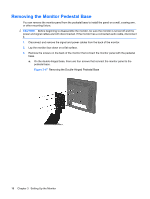
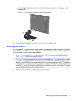
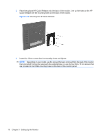
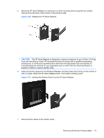
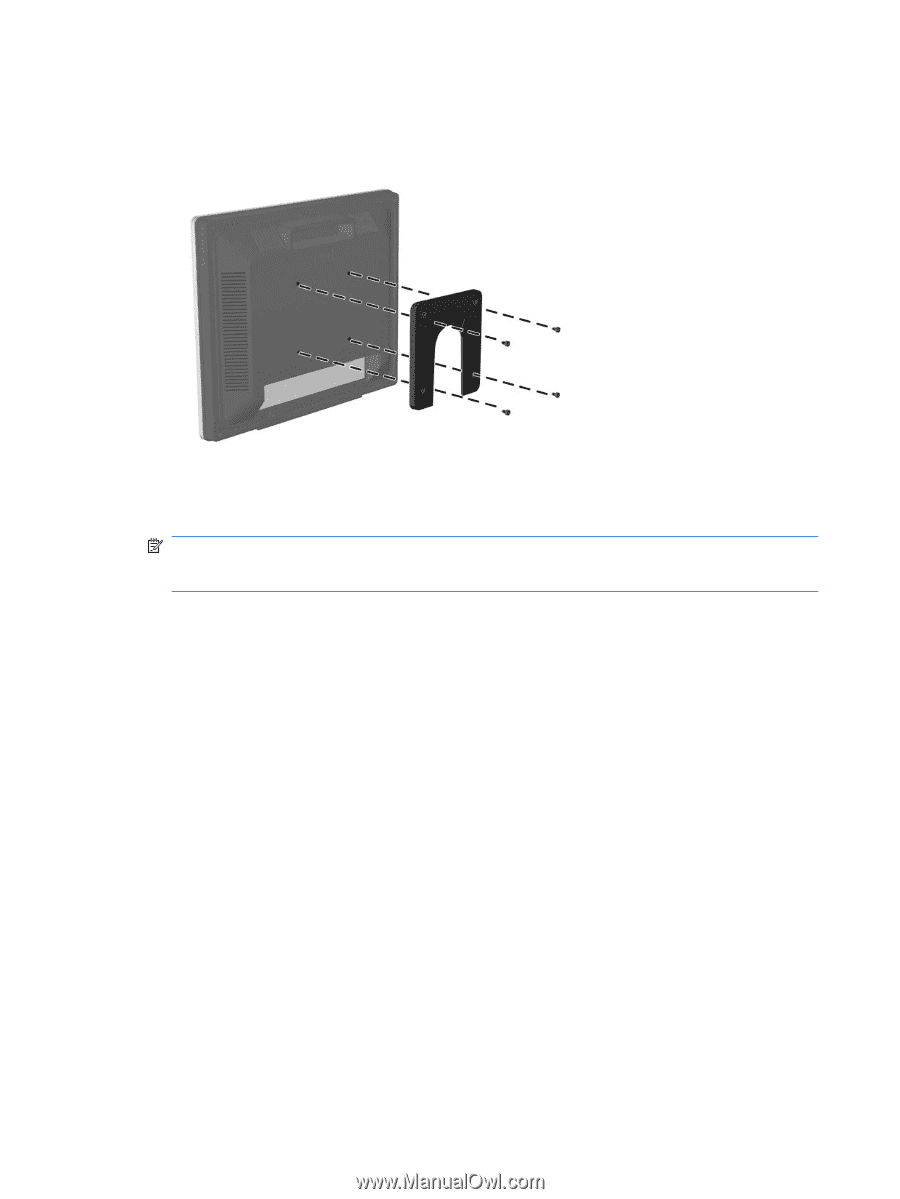
3. Place the optional HP Quick Release onto the back of the monitor. Line up the holes on the HP Quick Release with the mounting holes on the back of the monitor. Figure 3-19 Mounting the HP Quick Release 4. Insert four 10mm screws into the mounting holes and tighten. NOTE: Depending on your model, use the screws that were removed from the back of the monitor that connected the monitor panel with the pedestal base, or use the four M4 x 10 mm screws that are provided in the VESA mounting holes on the back of the monitor panel. 18 Chapter 3 Setting Up the Monitor
-
 1
1 -
2
-
3
-
4
-
5
-
6
-
7
-
8
-
9
-
10
-
11
-
12
-
13
-
14
-
15
-
16
-
17
-
18
-
19
-
20
-
 21
21 -
 22
22 -
 23
23 -
 24
24 -
 25
25 -
 26
26 -
 27
27 -
 28
28 -
 29
29 -
 30
30 -
 31
31 -
32
-
33
-
34
-
35
-
36
-
37
-
38
-
39
-
40
-
41
-
42
-
43
-
44
-
45
-
46
-
47
-
48
-
49
-
50
-
51
-
52
-
53
-
54
-
55
-
56
-
57
-
58
-
59
-
60
-
61
-
62
-
63
-
64
-
65
-
66
-
67
 |
 |
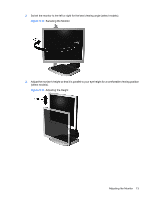
3.
Place the optional HP Quick Release onto the back of the monitor. Line up the holes on the HP
Quick Release with the mounting holes on the back of the monitor.
Figure 3-19
Mounting the HP Quick Release
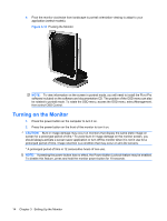
4.
Insert four 10mm screws into the mounting holes and tighten.
NOTE:
Depending on your model, use the screws that were removed from the back of the monitor
that connected the monitor panel with the pedestal base, or use the four M4 x 10 mm screws that
are provided in the VESA mounting holes on the back of the monitor panel.
18
Chapter 3
Setting Up the Monitor