HP LC2000r LP2000r Fan Connector Diagram - Page 1
HP LC2000r - NetServer - 128 MB RAM Manual
 |
View all HP LC2000r manuals
Add to My Manuals
Save this manual to your list of manuals |
Page 1 highlights
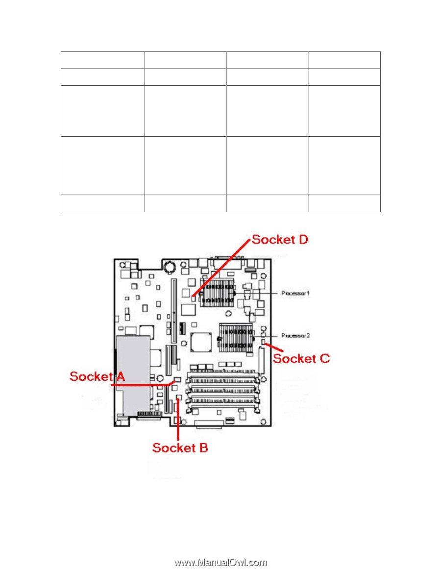
Physical Fan System Board Connector Event Log Notation Fan and Connector Silkscreen Photo Fan that cools the PCI CHA_Fan 1 Chassis Fan 1, Fan Connector A (see cage figure below) Front (closest to the CHA_Fan 2 Chassis Fan 2 Fan Connector B floppy drive) CPU fan (see figure below) (This is the only CPU fan in LP2000r systems with 866 MHz, 933 MHz and 1 GHz processors) Rear (Furthest from the CPU_Fan 2 CPU Fan 2, Fan Connector C floppy drive) CPU Fan. (see figure below) This fan and system board socket should only be installed in LP2000r units with 1.13, 1.26 or 1.40 GHz CPU's **None No label for connector Not monitored Fan Connector D **(see figure below) ** This fan socket is not labeled on the system board. DO NOT use this connector. It will provide power to the fan, but this connector is not monitored, so if a fan failure occurs no errors will be generated.
-
 1
1
 |
 |