HP LH3000r HP Netserver LXr 8500 Technical Reference Label - Page 1
HP LH3000r - NetServer - 128 MB RAM Manual
 |
View all HP LH3000r manuals
Add to My Manuals
Save this manual to your list of manuals |
Page 1 highlights
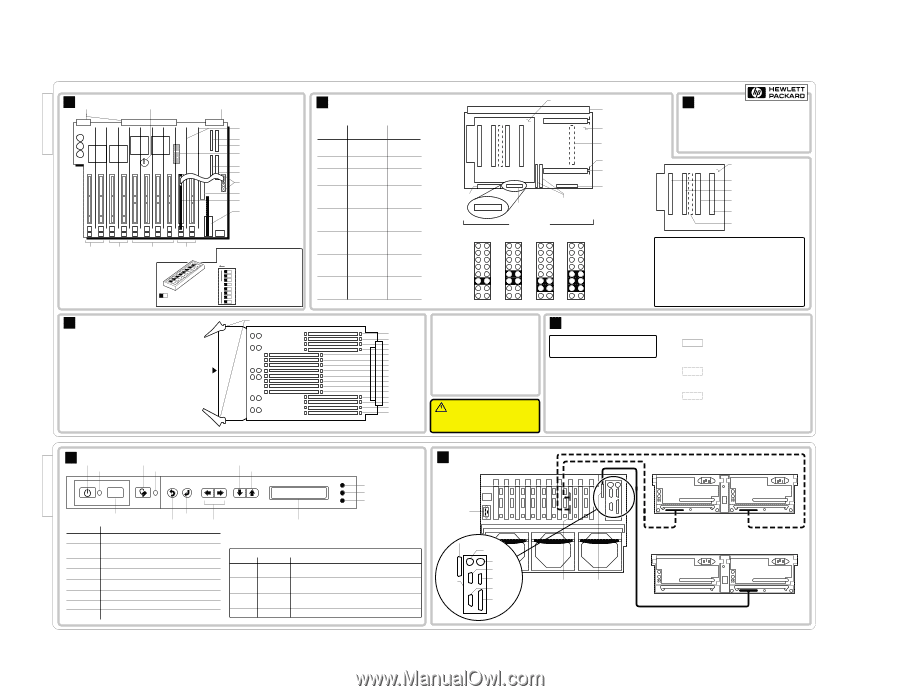
D7054-80206, Rev B HP NetServer LXr 8500 Technical Reference Label A I/O Baseboard Connectors to Midplane Board CMOS Battery (under I/O Baseboard Shield) Connector to Midplane Board PCI Slot Dividers (10) SCSI A IDE I/O Configuration Switches P10 P9 P8 P7 P6 P5 P4 P3 P2 P1 SCSI B Flexible Disk I2 C Connectors PCI LED Board Connector Top Tools RCC I/O Riser Board +3.3 VDC +3.3 VDC 33/66 MHz 33/66 MHz Bus 3 Bus 2 Note: If 66 MHz is selected (Setup Utility), but a 33 MHz card is present at boot time, the bus runs at 33 MHz. Buses can be dynamically allocated, which changes the defaults shown. All I/0 Slots are PCI Hot-Plug, 32 or 64 bit. All accept the Universal Card (which can accept a 3.3 VDC or 5 VDC signal). +5 VDC 33 MHz Bus 1 +5 VDC 33 MHz Bus 0 I/O Configuration Switches OPEN = OFF CLOSED = ON Shaded rectangle represents the depressed side of the rocker switch OPEN Reserved Recovery Boot Reserved Reserved CMOS Clear Password Clear PCI Hot-Plug Switch Disable Reserved D Memory DIMM Installation Guidelines • For up to eight DIMMs, use one memory board in either slot, left or right. (No terminator is required in the empty slot.) With one memory board, you can load DIMMs in any sequence, any slot, any size. • For more than eight DIMMs, a second memory board must be installed to prevent RFI and to maintain compliance with Electromagnetic Compatibility Standards. • If you are using two memory boards, you can leave one empty and install up to 16 DIMMs on the other memory board. • If you install DIMMs on both memory boards, configure both identically. If DIMMs of different sizes are present in the same-numbered sockets on both boards, a mismatch will be detected and mismatched DIMMs reconfigured to the lower value (or unpaired DIMMs will be ignored). Push here to start latches Memory Board Latches 12 15 16 12345678 OPEN B Processor Baseboard and Carrier Boards Left Processor Carrier Board Grand Connector Number of Processors (Add to Slot) 1 (L1) 2 (L2) 3 (L3) 4 (L4) 5 (R1) 6 (R2) 7 (R3) 8 (R4) Processors in Slots Listed L=Left R=Right L1 Terminators L2 L3 L4 L1 L3 L2 L4 L1 L4 L2 L3 L1 None L2 L3 Front Panel Board Connector L4 L1 R1 R2 L2 R3 L3 R4 L4 L1 R1 L2 R2 L3 L4 R3 R4 es, all covers and panels L1 R1 R4 L2 R2 L3 R3 L4 L1 R1 L2 R2 L3 R3 L4 R4 None L1 L2 L3 L4 J6A1 Jumper Block on Processor Basebord Front of Board Jumper Block J6A1 12 34 56 78 9 10 11 12 13 14 15 16 400MHz 12 34 56 78 9 10 11 12 13 14 15 16 450MHz 12 34 56 78 9 10 11 12 13 14 15 16 500MHz Processor Baseboard Processor Carrier Board Connector (for Right) Locking Bar Release Processor Cage Locking Bar Unused Cache Coherency Filter Connectors 12 34 56 78 9 10 11 12 13 14 15 16 550MHz C Boot Order Boot Order 1. Primary IDE CD-ROM 2. Flexible Disk 3. PCI Slot 1 4. PCI Slot 2 5. Embedded SCSI SCSI A SCSI B 6. PCI Slot 3 7. PCI Slot 4 8. PCI Slot 5 9. PCI Slot 6 10. PCI Slot 7 11. PCI Slot 8 12. PCI Slot 9 13. PCI Slot 10 R1 R2 R3 R4 Right Processor Carrier Board for Processor 5 for Processor 6 for Processor 7 for Processor 8 Processor Carrier Board Connector (backside) Caution: In a multiple processor configuration, the processors all must be the same HP product number, the same frequency, and the same cache size. Processors 1 - 4 should be mounted on the left Processor Carrier Board. Processors 5 - 8 should be added to the Right Processor Carrier Board. See the table in this panel. Operating a CPU chip at a lower or higher speed, or at an incorrect voltage, may result in unreliable operation -- or cause catastrophic or hidden damage to the chip. Repairs due to unauthorized jumper settings or use of incorrect processor combinations are not covered under the warranty. Processors supplied and warranted by HP for NetServers have an HP label. Memory DIMMs: Slot J16 Slot J15 Slot J14 Slot J13 Slot J12 Slot J11 Slot J10 Slot J9 Slot J8 Slot J7 Slot J6 Slot J5 Slot J4 Slot J3 Slot J2 Slot J1 Audience Assumptions This Service Reference Label is for trained service personnel. Hewlett-Packard Company assumes you are qualified in the servicing of computer equipment and trained in recognizing hazards in products with hazardous energy levels. Electrostatic Discharge To avoid catastrophic or hidden damage to components, wear a wrist strap and use a static-dissipative work surface connected to the chassis when handling components. Use an antistatic service kit, such as 3M® 8501/8502/8505 or equivalent. Even at low room temperatur must be in place to provide controlled airflow for system reliability. This information is subject to change without notice and is provided without warranty. ©1999, Hewlett-Packard Company. All rights reserved. CAUTION! Do not remove top cover while unit is on. (PCI access panel can be removed.) E Power Supply Modules Caution: If you remove a power supply, wait at least 15 seconds to reset before reinserting it. Power Supply Configuration • AC Input to power supply is 200V - 240V • Two power supplies (minimum) are required • Power supplies can be installed in any power supply bay • A power supply must be installed in each bay at all times to ensure proper system cooling Power Supply LEDs: PWR AC Input Indicator Green = AC power input to module OK. Blinking Green = AC power input to system OK. System in standby mode. Off = No AC power. PRFL Predictive Fail Blinking Yellow = Power supply fan is slow. Power supply may fail. Off = Fan speed normal. FAIL Attention Indicator Off = Normal operation. Yellow = Power supply failure. Blinking Yellow = Current limit exceeded. Possible short in power supply or server. D7054-80206, Rev B D7054-80208, Rev A F Control Panel Power Button Power LED Secure Mode Button Secure Mode LED Reset Scroll Down One Line Scroll Up One Line "Traffic Light" LEDs: Red Yellow Green Reset Button Control Buttons and LEDs Control Description Power Button Turns system power on and off. Enter Escape Not Used Power LED Reset Steady green when power is on; flashing green when system is in ACPI Sleep; off when system power is off. Performs a system hard reset. Secure Mode Button Secure Mode LED Escape Puts the system in Secure Mode, if the system was configured for Secure Mode. Glows steady green when the system is in Secure Mode. Return to previous menu. Enter Down Arrow and Up Arrow Select an item from the menu. Scrolls the display down one line or up one line. "Traffic Light" LEDs Red Yellow Off Off Flashing Off Off Flashing Off Off Two Line Display Display works even when the server has powered down or hung, as long as the server has standby power. Green Off Off Off On Main Power is off. System may or may not have standby power. A system component has failed. If the component was redundant (i.e., a power supply or fan), the system may still be operating. A condition exists which may cause the failure of a system component. The system is operating normally. G Rear Panel and Cabling HP NetServer LXr 8500 (rear) AC In External SCSI Port Keyboard * I/O Riser Board Mouse * Serial B Serial A VGA DAC Board Parallel Port * Keyboard and Mouse ports are interchangeable SCSI Connector Dual-Bus Configured Storage Single-Bus Configured Storage D7054-80208, Rev A
-
 1
1
 |
 |