HP LH4r HP Netserver LC 2000 Technical Reference Card - Page 1
HP LH4r - NetServer - 256 MB RAM Manual
 |
View all HP LH4r manuals
Add to My Manuals
Save this manual to your list of manuals |
Page 1 highlights
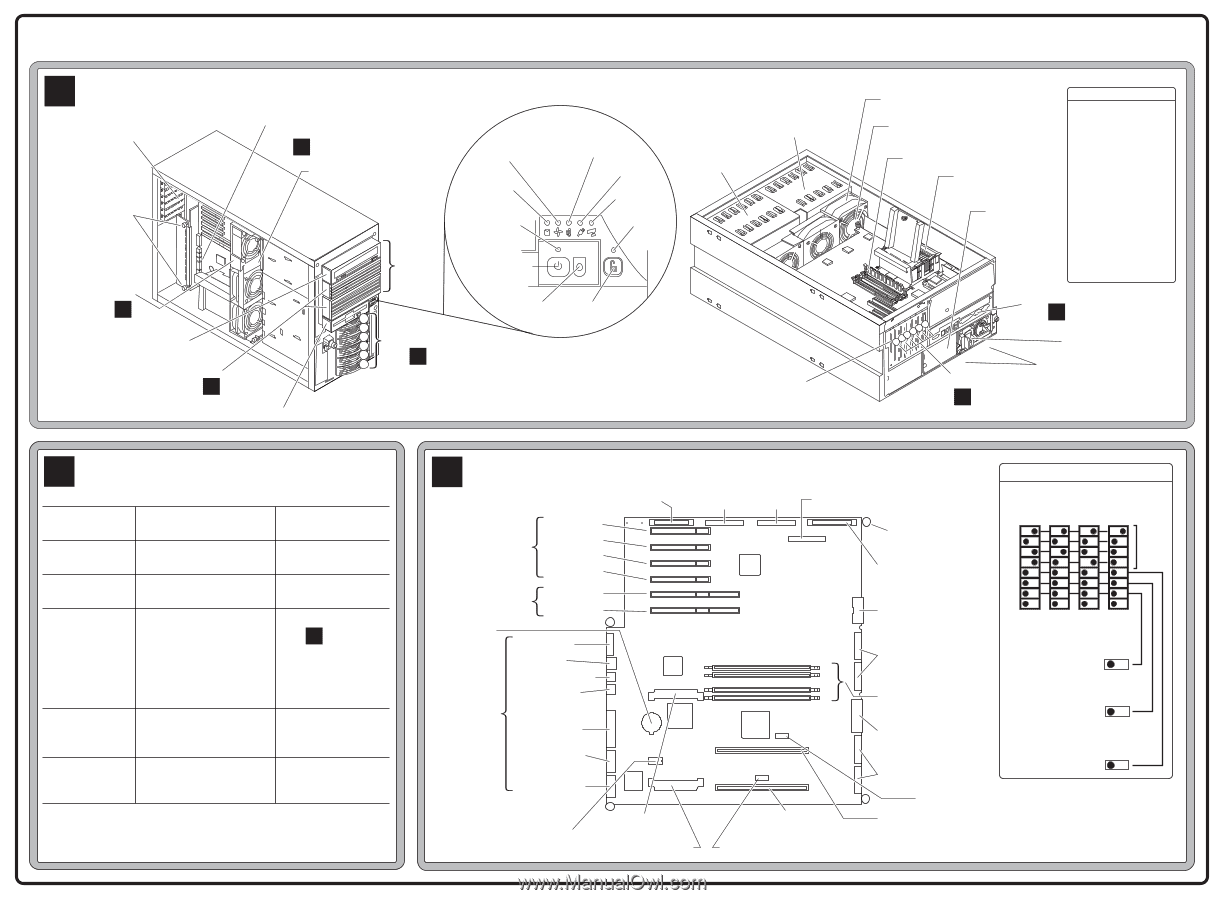
HP NetServer LC 2000 & LC 2000r Technical Reference Card HP Product No. D8514-80201, REV B, Sept. 1999 A Cabinet Pedestal Version 6 PCI Slots System Board Release Screws (2 of 4) I/O Connectors Rear of System Board See C Fan Module Rack Version Front Hot-Swap Mass Panel Display Storage Cage Non-Hot- Fan Fail Overtemperature Swap Mass Hard Disk Power Storage Cage Activity Reserved Power Indicator Secure Mode System and I/O Board Shevles Power RESET 1 - 4 On/Off/Sleep See C Shelf 1: IDE CD-ROM Drive Shelves 2 & 3: Optional Mass Storage See B Shelf 4: Flexible Disk Drive RESET 6 5 Hot-Swap HDD 4 3 Slots 1 - 6 2 See D 1 (Front View) Reset Keyboard Lock Caution: Do not operate server for more than 2 minutes with any cover (including Power Supply Bays and Disk Drives) removed. Processor will shut down if overheated. Knockout for External SCSI Fan Assembly System Board Release Screw (1 of 4) DIMM Slots Processor Optional Redundant Power Supply Default Boot Order 1. IDE CD-ROM 2. FDD 3. SCSI A Bus • SCSI Device ID 0 • SCSI Device ID 9 4. SCSI B Bus • SCSI Device ID 0 • SCSI Device ID 9 5. PCI Slot P1 6. PCI Slot P2 7. PCI Slot P3 8. PCI Slot P4 9. PCI Slot P5 10. PCI Slot P6 1234 56 1 2 PCI Slots See C I/O Connectors See C Power Connector Power Supplies (Rear View) B Mass Storage Device Locations and Settings Device Location in order of recommendation Standard Shelf 1 IDE CD-ROM Standard Shelf 2 Hard Disk Drive HP Accessory 9.1 GB HDD HP Accessory 18.2 GB HDD HP Accessory 36.4 GB HDD Hot-Swap HDD Slot 1, 2, 3, 4, 5, 6 6 Low-Profile, 3 Half-Height Drives, or mix LP/HH Additional SCSI device Shelf 3 Standard Dual Embedded Channel SCSI Controller Device Settings Set to Master (Default) SCSI ID 0 (Default) For additional HDD, See D For SureStore, SCSI ID 2 For DAT, SCSI ID 4 SCSI ID 7 See documentation with each device for further configuration information. C System and I/O Board Flexible Disk Drive 32-bit PCI Slot 1 PCI Slot 2 PCI Slot 3 PCI Slot 4 64-bit CMOS Battery I/0 Connectors PCI Slot 5 PCI Slot 6 * Video LAN Keyboard Mouse Parallel Serial Connector Management Port * Secondary Configuration VRM Switch Primary VRM SCSI A SCSI B Configuration Switch Front Panel Connector * System Board Assembly Release Screws (4) IDE CD-ROM Fan Connector Switch 8 Off = 133MHz FSB 533 600 667 733 1 2 CPU 3 Speed 4 5 6 7 8 OFF ON OFF ON OFF ON OFF ON Optional Redundant Power Supply 3 2 Connectors 1 0 DIMM Slots Test Only (7) Password (6) Clear Password Power Connector For Mass Storage Power Supply Connectors Config. Memory (5) Clear Config. (CMOS) Primary Processor Slot * Secondary Temperature Sensor (U43) Secondary Processor Slot Primary Temperature Sensor (U51) For additional information, see other side.
-
 1
1 -
 2
2
 |
 |