HP LH4r HP Netserver LH 4r Installation Road Map - Page 5
Install Additional Mass Storage Devices, Non-Hot-Swap SCSI Addressing, Hot-Swap Module
 |
View all HP LH4r manuals
Add to My Manuals
Save this manual to your list of manuals |
Page 5 highlights
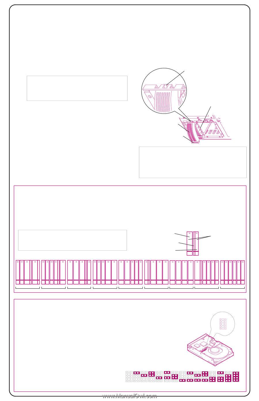
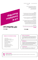
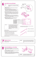
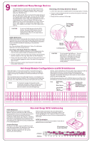
9 Install Additional Mass Storage Devices This HP NetServer supports both hot-swap SCSI devices, Removing a Hot-Swap Disk Drive Module installed in the hot-swap mass storage cage, and non-hot swap SCSI devices, installed in shelves 3 and 4 (located 1. Let the drive spin down completely before removing it (about 1 minute). below the CD-ROM drive). 2. Press in on the locking latch at the end of the drive ejector handle and Use only Ultra2 (LVD), SCA-2 connector hot-swap devices in gently open the handle. the hot-swap mass storage cage. You can use any standard (non-Ultra2) wide, 68-pin single-ended SCSI device in non- 3. Slowly pull the module out of the cage. hot-swap shelves 3 and 4, such as a removable hard disk or a tape backup drive. Narrow (50-pin) SCSI devices are supported in the non-hot-swap shelves, but require a 68-to- 50-pin cable adapter for connecting the data cable to the device. (One adapter is provided on the SCSI cable behind shelf 3.) Pin Engages Hole in Edge of Cage CAUTION Do not mix Ultra2 devices with other SCSI devices. Use only Ultra2 devices in the hotswap mass-storage cages. Use only nonUltra2 devices in the non-hot-swap shelves (shelves 3 and 4). SCSI Addressing Different form-factor hot-swap disk drive modules can be mixed and matched within the hot-swap mass storage cage. Because so many different configurations are possible, the SCSI address assigned to each module will be different depending on the particular configuration. See "Non-Hot-Swap SCSI addressing," below, for addressing restrictions for non-hot-swap devices. Inserting a Hot-Swap Disk Drive Module 1. Open the drive module by pressing in on the locking latch at the end of the drive ejector handle and pulling open the handle. 2. Choose a location in the hot-swap mass-storage cage and gently slide the module into the cage. Stop when you feel resistance. 3. Slowly close the ejector handle. Verify that the pin behind the pivot end of the handle engages the hole in the edge of the cage (see figure at right). 4. With even pressure, gently close the ejector handle until the locking latch clicks shut. Disk Drive Module Ejector Handle Locking Latch CAUTION Do not operate this NetServer -- for even short periods -- without a drive module, filler panel, or drive spacer in every hotswap and non-hot-swap mass storage location. Otherwise, damage to components may result due to improper cooling airflow. Hot-Swap Module Configurations and SCSI Addresses Both half-height (1.6-inch) and low-profile (1-inch) devices may be installed in the hot-swap mass-storage cage. There are two different height hot-swap trays available to accommodate different form-factor devices. Six low-profile devices or four half-height devices, or combinations of these two devices may be installed in the hot-swap mass-storage cage. Because of the height difference between half-height and low-profile devices, some combinations of the two types require spacers to take up space between devices. The figure below shows the possible combinations of hot-swap devices possible. SCSI addresses are assigned automatically depending on the location of a drive module within the mass storage cage. SCSI addresses listed here are for SCSI A channel only. Refer to the HP NetServer LH 4/LH 4r User Guide for SCSI B channel addresses. NOTE For maximum storage density and to avoid configuration problems, install hot-swap drives in consecutive locations only, beginning with the leftmost location in the mass-storage cage. Key: Half-Height Tray Drive Spacer Low-Profile Tray or Filler Panel 38 Numbers On the Modules Indicate Assigned SCSI Addresses 0 1 3 8 012 3 8 0 1 3 9 012 3 8 0 1 389 0 1 3 8 0 1 3 8 0 2 389 01 2389 Non-Hot-Swap SCSI Addressing SCSI Addresses Each SCSI device must have a unique SCSI Refer to the documentation that came with the SCSI address. Devices connected to the SE connector device for the jumper location and settings. Refer to the (those located on the non-hot-swap shelves) and to Technical Reference Card, located in the pouch on the the SCSI B connector (not used in the factory- inside of the NetServer cover, for the recommended SCSI configured models) share one SCSI bus. Therefore, addresses. each device connected to either of these connectors must have a unique address (narrow devices may use addresses 0-6; wide devices may use addresses 0-15, except address 7). SCSI Termination The NetServer SCSI cable is terminated. Verify that no added devices are terminated. JUMPERS A0 A1 A2 A3 Jumper Settings The figure to the right is typical of a SCSI hard disk drive that may be used in this NetServer. Use this as a general reference for jumper locations and settings. Typically, jumpers A0, A1, A2, and A3 determine the SCSI address. (Drive typical; your model may differ) A0 Jumpers: A1 A2 A3 Address: 0 12 34 56 8 9 10 11 12 13 14 15
-
 1
1 -
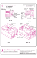 2
2 -
 3
3 -
 4
4 -
 5
5 -
 6
6
 |
 |