HP LH4r HP Netserver LP 2000r Technical Reference Label - Page 1
HP LH4r - NetServer - 256 MB RAM Manual
 |
View all HP LH4r manuals
Add to My Manuals
Save this manual to your list of manuals |
Page 1 highlights
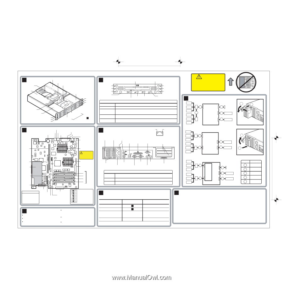
100.0mm REF HP Netserver LP 2000r Technical Reference Label A Netserver Air Flow Guide PCI Cage Power Supplies CHA_FAN2 System Board SCSI Cage Slot 3 Slot 4 Slot 5 CHA_FAN1 SCSI Cage Slot 0 Slot 1 Slot 2 Flexible Disk Drive CD-ROM Front Panel See Panel B for Control Panel C Control Panel Flexible Disk Drive Power Switch Disk 0 Disk 1 Disk 2 Reset Temperature/Fans hp netserver lp2000r Power SCSI Supply Activity Disk 3 Disk 4 Disk 5 Power Control Panel LED Definitions Power Steady green when operating normally. Flashing green at 1 Hz rate in sleep mode. SCSI Activity Disks Temperature/Fans Power Supply Flashing green when there is SCSI activity. Off when there is no activity. Steady green when drive is present. Off when drive is not present. Steady red for faulty drive or rebuild failure. Alternating green and red at 1 Hz rate for SCSI rebuild. Alternating green and red at 3 Hz rate indentifies drive. Steady green for normal operation. Steady red indicates overtemperature, or fan failure. Alternating green and red indicates warning. Steady green indicates normal operation. Alternating green and red indicates power supply warning. Steady red indicates power supply failure. B System Board LAN B Battery Serial B LAN A/Mgmt Video Parallel Serial A/ Mgmt. USB (2) Mouse (upper) Keyboard (lower) PCI Riser Card IDE-2 Integrated Remote Assistant Board PCI Cage Connector FDD Processor 1 CAUTION! Use a new thermal pad when reinstalling a heatsink Processor 2 Power Connector 0 1 DIMMs 2 3 D Rear Panel Activity LED Speed LED Power Power AC Power for PS 1 Supply 1 Supply 2 Mouse USB (2) Parallel Enlarged LAN Connector Serial B PCI Slots (3) B A Power LEDs Keyboard AC Power for PS 2 Video LAN B Serial A/Mgmt LAN A/Mgmt External SCSI Connector Rear Panel LED Definitions Power Steady green indicates normal operation. Flashing green indicates Standby Mode. Steady amber indicates power supply failure. LAN Activity Steady green indicates link is valid. Flashing green indicates activity on LAN. LAN Speed Steady amber indicates link rate of 100mbps. Off indicates link rate of 10mbps. CAUTION! Do not operate with power supply slot empty. Close the slot with a filler panel or a second power supply. G Standard SCSI Cabling HDD 0 HDD 1 HDD 2 HDD 3 HDD 4 HDD 5 3 SCSI A SCSI B 5 IDE-1 4 External SCSI 2 CD-ROM FDD System Board 1 FDD Duplex SCSI Cabling HDD 0 HDD 1 3 SCSI A HDD 2 HDD 3 HDD 4 5 SCSI B IDE-1 FDD 2 CD-ROM 1 FDD HDD 5 System Board DAC Duplex SCSI Cabling HDD 0 HDD 1 HDD 2 HDD 3 3 SCSI 0 SCSI B 4 External SCSI DAC IDE-1 2 CD-ROM HDD 4 5 SCSI 1 FDD 1 FDD HDD 5 System Board Power Supply Removal 2 3 1 1. Press in to release latch 2. Pull down latch 3. Slide Power Supply out Power Supply Insertion 2 1 1. Press in firmly 2. Push up latch to secure Cables 1 2 Type Flexible Disk Cable IDE CD-ROM Cable 3 SCSI Cable 4 Int / Ext SCSI Cable 5 SCSI Cable, Long SCSI B Boot Order 1. IDE CD-ROM 2. Flexible Disk Drive 3. Hard Drive 4. Bootable Cards 5. Network Connection SCSI A Air Flow Guide Connector IDE-1 Configuration Switch Not Used (Default = Off) BIOS Recovery Clear Password Clear CMOS Not Used (Default = Off) Not Used (Default = Off) Not Used (Default = Off) Not Used (Default = Off) Open = Off Closed = On F Memory Use only PC 133 HP DIMMs. The LP 2000r can support up to 4GB. DIMM sizes supported are 128MB, 256MB, 512MB, and 1GB. 4MB of standard video memory is provided with the embedded video controller. DIMMs may be installed in any combination in any DIMM socket. When handling DIMMs observe anti-static precautions. E Mass Storage Device Locations and Settings Device Location (in order of recommendation) Flexible Disk Drive Standard IDE CD-ROM Drive HP Accessory 9 GB HDD or HP Accessory 18 GB HDD or HP Accessory 36 GB HDD See Panel A See Panel A Slot 0 through 5 Standard Dual SCSI Controller Embedded Device Settings Factory installed Factory Installed Drives may be installed in Slot 0 through 5. SCSI ID 7 See documentation with each device for further configuration information. H Service Information Electronic Support Services • Internet Web Page http://www.hp.com/go/netserver • Internet FTP ftp://ftp.netserver.hp.com • Compuserve Library GO HPPC • HP Navigator CD Support Questions • HP-Authorized Reseller • Compuserve Discussion Forum GO HPPC • US / Canada Phone Support 1-970-635-1000 • Europe Phone Support (+31-20) 581-3330 HP has offices in over 100 countries. (Netherlands) Check your local telephone directory. Selected HP Accessories For other tested accessories, download the Order Assistant from the HP Web page. Audience Assumptions This Technical Reference Label is for trained service personnel. Hewlett-Packard Company assumes you are qualified in the servicing of computer equipment and trained in recognizing hazards in products with hazardous energy levels. Electrostatic Discharge (ESD) Warning To avoid catastrophic or hidden damage to components, wear a wrist strap and use a static-dissipative work surface connected to the chassis when handling components. Use an antistatic service kit, such as 3M® 8501/ 8502/8505 or equivalent. This information is subject to change without notice and is provided without warranty. © Copyright 2000 Hewlett-Packard Company P1824-80221 Label Manufacturer to print part number in Code 39 barcode here 100.0mm REF OPEN
-
 1
1
 |
 |