HP LH4r HP Netserver LPr Technical Reference Card
HP LH4r - NetServer - 256 MB RAM Manual
 |
View all HP LH4r manuals
Add to My Manuals
Save this manual to your list of manuals |
HP LH4r manual content summary:
- HP LH4r | HP Netserver LPr Technical Reference Card - Page 1
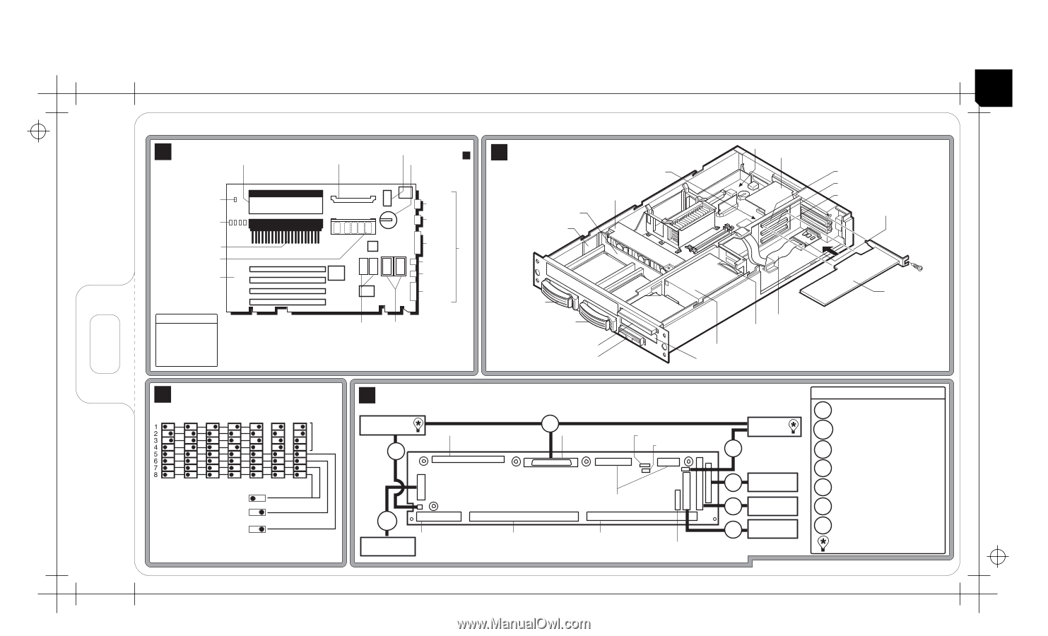
ALA SP 85/2400 OM HP NetServer LPr Technical Reference Card A Bay SCSI ID# 1 Regulator Module CD-ROM Drive Floppy Disk Drive I/O Board *D9431-80204* D9431-80204 System Board C System Switches (Default Settings) CPU Frequency (by MHz) * 500 550 600 650 700 750 800 CPU Speed Test Only (7 & 8)
-
 1
1
 |
 |
HP
219239
FRONT SIDE
PN D9431-80204
6.181 X 11.811
DC 1682 ALA
SP
85/2400
OM
*D9431-80204*
HP NetServer LPr Technical Reference Card
CPU Frequency (by MHz)
D9431-80204
To Fan Pack
To System Board
To System Board
To System Board
Network Adapter Card
PCI Slot #4
Embedded SCSI
Controller
IPMI / I
C (optional)
2
I
C (optional)
2
From
Power Supply
SCSI
Backplane
IDE CD-ROM
Floppy Disk
Drive
Control Panel
MGMT
PORT
I
21
F81
D12
CP
Management
Port
C16
C18
SCSI Repeater
Card
*
DIMM LED on or flashing when
system is on and the corresponding
DIMM is installed.
System Switches
C
A
System Board
I/O Board and System Cabling
D
(Default Settings)
System
B
Part Nos.
Cabling Key
5183-6818
D12
IDE CD-ROM Cable
5183-6817
CP
Control Panel Cable
F81
Floppy Disk Drive
Cable
5183-6819
C18
SCSI Cable
5183-6820
C16
SCSI Repeater
Power Cable
5183-7652
I
21
I
C Cable to SCSI
Backplane
5183-6815
2
1.
2.
3.
4.
5.
6.
Boot Order
IDE CD-ROM
Floppy Drive
Embedded SCSI
PCI 1
PCI 2
PCI 3
**
For additional information, see other side.
D7082A Cable Kit
*
Extends embedded SCSI externally when
PCI SCSI Card controls internal bays.
Hot-Swap Bay
SCSI ID# 0
SCSI Repeater
Card
Fan Pack
Hot-Swap Bay
SCSI ID# 1
I/O Board
System Board
Network Adapter Card
PCI Slot #1
PCI Slot #2
PCI Slot #3
Floppy Disk Drive
CD-ROM Drive
Optional PCI
Card
SCSI Management
Card
Control Panel
Power Supply
Power Supply Fan
SCSI Cable
*
SCSI Backplane
Built-in SCSI Terminator
MGMT
PORT
Management Port
Cable
5183-6816
C
Monitor
Serial B
Serial A
Parallel
Mouse
Keyboard
Battery
System Switches
Secondary Processor
or Terminator
Secondary Voltage
Regulator Module
Socket
Primary Processor
Video
Memory
Primary Voltage
Regulator Module
Video
Memory Upgrade
DIMM Memory
Sockets
Standby Power LED
0
1
2
3
0123
DIMM LEDs
*
I/O
Remove Terminator and install
Secondary Voltage Regulator
Module to install Secondary
Processor.
**
Password (6)
Clear Password
CPU
Speed
Test Only (7 & 8)
ON
OFF
500
ON
OFF
550
ON
OFF
600
ON
OFF
650
ON
OFF
750
ON
OFF
800
ON
OFF
700
Config. Memory (5)
Clear Config. (CMOS)
NOTE:
For CPU Speeds > 800 MHz,
switch settings remain at 800 MHz settings
*
*