HP LH4r HP Netserver LPr Technical Reference Card - Page 1
HP LH4r - NetServer - 256 MB RAM Manual
 |
View all HP LH4r manuals
Add to My Manuals
Save this manual to your list of manuals |
Page 1 highlights
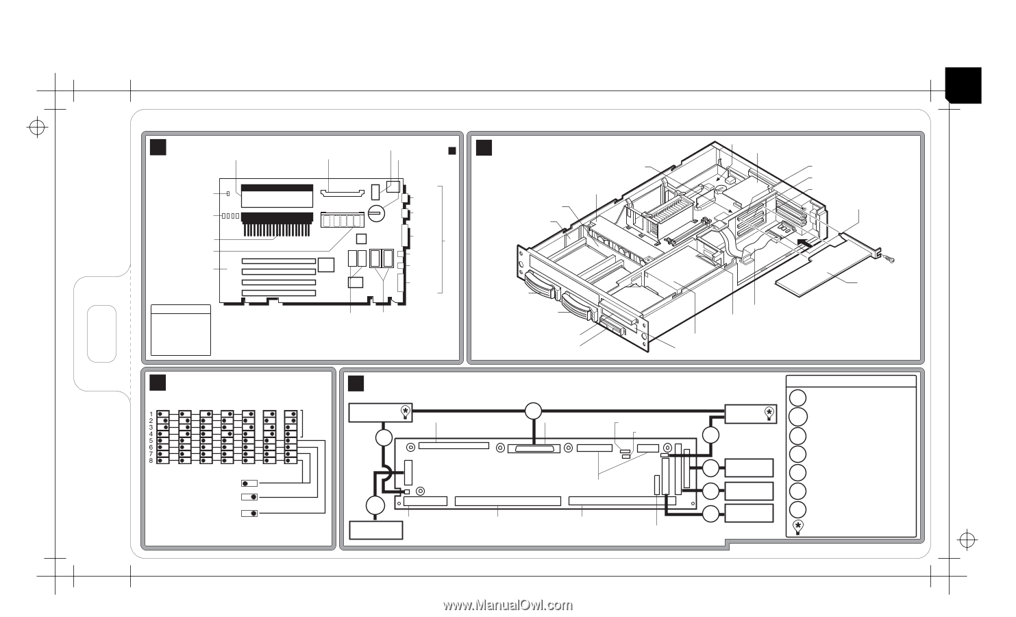
HP 219239 FRONT SIDE PN D9431-80204 6.181 X 11.811 DC 1682 ALA SP 85/2400 OM HP NetServer LPr Technical Reference Card A System Board Secondary Processor or Terminator * * System Switches C Secondary Voltage Regulator Module Socket Battery Standby Power LED Serial B DIMM LEDs* 0123 Serial A Primary Processor Primary Voltage 0 DIMM Memory Sockets 1 2 3 Parallel I/O Mouse Keyboard Monitor Boot Order 1. IDE CD-ROM 2. Floppy Drive 3. Embedded SCSI 4. PCI 1 5. PCI 2 6. PCI 3 * DIMM LED on or system is on and flashing when the corresponding DIMM is installed. Video Video Memory Memory Upgrade * * Remove Terminator and install Secondary Voltage Regulator Module to install Secondary Processor. B System Fan Pack SCSI Backplane SCSI Management Card Hot-Swap Bay SCSI ID# 0 Hot-Swap Bay SCSI ID# 1 Regulator Module CD-ROM Drive Floppy Disk Drive I/O Board *D9431-80204* D9431-80204 System Board Network Adapter Card PCI Slot #3 PCI Slot #2 PCI Slot #1 SCSI Repeater Card SCSI Cable* Power Supply Fan Optional PCI Card Power Supply Control Panel * D7082A Cable Kit Extends embedded SCSI externally when PCI SCSI Card controls internal bays. OFF ON OFF ON OFF ON OFF ON OFF ON OFF ON OFF ON C System Switches (Default Settings) CPU Frequency (by MHz) * 500 550 600 650 700 750 800 CPU Speed Test Only (7 & 8) Password (6) Clear Password Config. Memory (5) Clear Config. (CMOS) * NOTE: For CPU Speeds > 800 MHz, switch settings remain at 800 MHz settings D I/O Board and System Cabling SCSI Repeater Card C16 Network Adapter Card PCI Slot #4 C18 Embedded SCSI Controller IPMI/ I 2 C (optional) I 2C (optional) SCSI Backplane I 21 Cabling Key Part Nos. C16 SCSI Repeater Power Cable MGMT Management Port PORT Cable 5183-7652 5183-6816 C18 SCSI Cable 5183-6820 MGMT PORT Management Port To System Board To System Board From Power Supply To System Board D12 IDE CD-ROM F81 Floppy Disk Drive CP To Fan Pack Control Panel I 21 I2 C Cable to SCSI Backplane F81 Floppy Disk Drive Cable 5183-6815 5183-6819 D12 IDE CD-ROM Cable 5183-6817 CP Control Panel Cable 5183-6818 Built-in SCSI Terminator For additional information, see other side.
-
 1
1
 |
 |