HP LH4r HP Netserver LXr 8000 Technical Reference Label - Page 1
HP LH4r - NetServer - 256 MB RAM Manual
 |
View all HP LH4r manuals
Add to My Manuals
Save this manual to your list of manuals |
Page 1 highlights
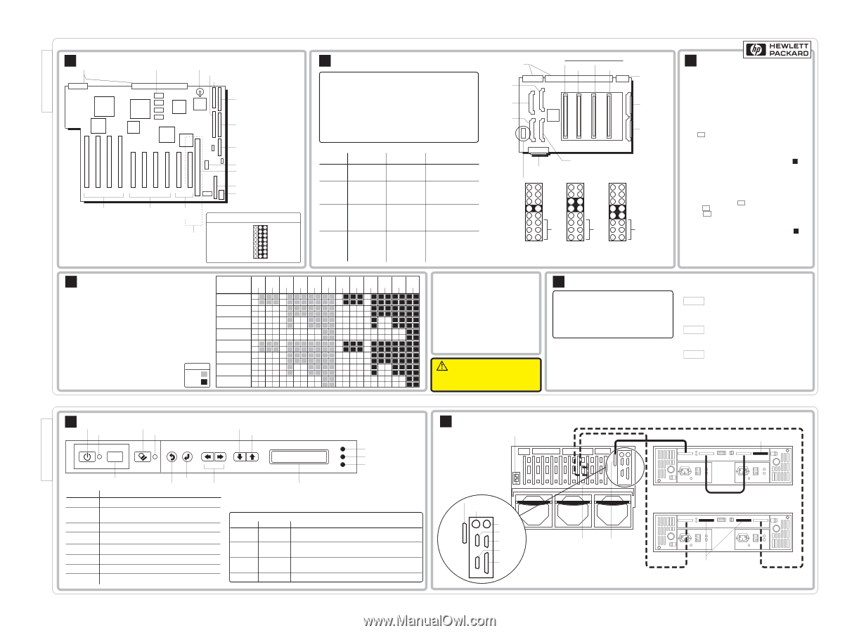
D6021-80209, Rev C, 1 of 2 HP NetServer LXr 8000 Technical Reference Label A I/O Baseboard Connectors to Midplane Board 2MB Video RAM Battery SCSI Channel B SCSI Channel A A B IDE Floppy Disk Unused Jumper Block ISA Slot P10 P9 P8 P7 P6 P5 P4 P3 P2 P1 Bus 2 64 Bit Hot-Plug PCI Bus Bus 1 Bus 0 Secondary 32 Bit Primary 32 Bit PCI Bus PCI Bus Shared PCI P1 & ISA Slot I/O Riser Slot BIOS USB I/O Baseboard Configuration Jumper Setting (Jumper shown with default settings) Update BMC Code 1 BIOS Recovery 2 Normal Boot Spare Jumper 3 Spare Jumper Flash VPP = No Write 4 Flash VPP= +12V CMOS Clear 5 Clear CMOS Password 6 PHP Switch Override 7 Enable SPI Chain 8 ABC B Processor Baseboard Caution: In a multiple processor configuration, the processors all must have the same HP product number, frequency, and cache size. For each additional processor, also add one voltage regulator module to the processor baseboard. Operating a CPU chip at a lower or higher speed, or at an incorrect voltage, may result in unreliable operation -- or cause catastrophic or hidden damage to the chip. Repairs due to unauthorized jumper settings or use of incorrect processor combinations are not covered under the warranty. Processors supplied and warranted by HP for NetServers have an HP label. Connectors to Midplane VRM 2 (Cache 3/4) VRM 1 (Cache 1/2) VRM 4 (Core 2) Processor Slots: Proc 1 Proc 3 Proc 2 Proc 4 Connector to Midplane VRM 6 (Core 4) VRM 5 (Core 3) Number of Processors Processors 1 Proc 1 2 Proc 1 Proc 2 3 Proc 1 Proc 2 Proc 3 4 Proc 1 Proc 2 Proc 3 Proc 4 Terminators Proc 2 Proc 3 Proc 4 Proc 3 Proc 4 Proc 4 None VRMs VRM 1 (Cache 1/2) VRM 2 (Cache 3/4) VRM 3 (Core 1) VRM 1 (Cache 1/2) VRM 2 (Cache 3/4) VRM 3 (Core 1) VRM 4 (Core 2) VRM 1 (Cache 1/2) VRM 2 (Cache 3/4) VRM 3 (Core 1) VRM 4 (Core 2) VRM 5 (Core 3) VRM 1 (Cache 1/2) VRM 2 (Cache 3/4) VRM 3 (Core 1) VRM 4 (Core 2) VRM 5 (Core 3) VRM 6 (Core 4) VRM 3 (Core 1) Front Panel Connector Jumper Block J31 VRM = Voltage Regulator Module 12 12 12 34 34 34 56 56 56 78 78 78 9 10 9 10 9 10 11 12 13 14 15 16 11 12 13 14 15 16 11 12 13 14 15 16 Pins 11- 16 are unused; spare jumpers may be placed here Jumper Settings for Jumper Settings for 400MHz Processors 450MHz Processors Jumper Settings for 500MHz Processors Your processor may require a BIOS change. Always use the correct BIOS version. (Refer to the Navigator CD-ROM received with your processor.) C Firmware Boot Order 1. IDE CD-ROM 2. Flexible Disk 3. ISA Board 3a. P1 3b. On-Board SCSI A 3c. On-Board SCSI B 3d. P2 4. P1 5. On-board SCSI A 6. On-board SCSI B 7. P2 - P10 ROM Setup Press F2 to enter Setup when prompted during Power On Self-Test. Clear CMOS Method 1 1. Change Jumper 5 in I/O Baseboard jumper block from B-C to A-B ("CMOS CLEAR" position). See Panel A . 2. Power up the system. 3. Allow the system to boot. 4. Power down the system. 5. Reset Jumper 5 to B-C. 6. Power up the system. Method 2 1. Power up the system. 2. When prompted, press F2 to enter Setup. 3. Press F9 for default CMOS settings. 4. Press F10 to save default settings and exit Setup. BIOS Boot Recovery 1. Change Jumper 2 in I/O Baseboard jumper block from B-C to A-B ("BIOS Recovery" position). See Panel A . 2. Put bootable diskette with BIOS file in flexible disk drive. 3. Power up the system. 4. System will beep three times; wait for all activity on the flexible drive to cease. 5. Power down the system. 6. Reset Jumper 2 from A-B to B-C ("Normal Boot" position). D Memory Common Memory Configurations: DIMM Installation Guidelines • Both Left and Right boards must be in place; Left may be empty • Add DIMMs to a board in groups of four • Fill banks in A, B, C, D order • All DIMMs in a bank must be identical size and speed • Banks of 64MB and 256MB DIMMs can be mixed on the same board; the banks may be in any order • 8-way interleave if the configurations of the two boards are identical; 4-way interleave otherwise The following HP DIMMs are supported: • D6112A 64MB DIMM (256MB DIMM Kit, 4x64) • D6114A 256MB DIMM (1GB DIMM Kit, 4x256) Key 64MB 256MB Total Memory 256MB 0.5GB 0.7GB 1GB Interleave 4 4 4 8 Board L R L R L R L R Bank A J1 J2 Bank B J5 J6 Bank C J9 J10 Bank D J13 J14 Bank A J3 J4 Bank B J7 J8 Bank C J11 J12 Bank D J15 J16 1.5GB 2GB 8 8 LRLR 1GB 4 LR 2GB 8 LR 3GB 4 LR 4GB 8 LR 6GB 8 LR 8GB 8 LR Audience Assumptions This Service Reference Label is for trained service personnel. Hewlett-Packard Company assumes you are qualified in the servicing of computer equipment and trained in recognizing hazards in products with hazardous energy levels. Electrostatic Discharge To avoid catastrophic or hidden damage to components, wear a wrist strap and use a static-dissipative work surface connected to the chassis when handling components. Use an antistatic service kit, such as 3M® 8501/8502/8505 or equivalent. Even at low room temperatures, all covers and panels must be in place to provide controlled airflow for system reliability. This information is subject to change without notice and is provided without warranty. ©1998, Hewlett-Packard Company. All rights reserved. CAUTION! Do not remove top cover while unit is on. (PCI Hot Plug access panel can be removed.) E Power Supply Modules Caution: If you remove a power supply, wait at least 15 seconds before reinserting it. (The delay gives the power supply's inrush protection circuit time to reset itself. Otherwise, the supply may trip the main circuit breakers or UPS circuit breakers.) Power Supply Configuration • AC Input to power supply is 220V only • A minimum of two power supplies are required • Power supplies can be installed in any power supply bay • A power supply must be installed in each bay at all times to ensure proper system cooling Power Supply LEDs: PWR AC Input Indicator Green = AC power input to module OK. Blinking Green = AC power input to system OK. System in standby mode. Off = No AC power. PRFL Predictive Fail Blinking Yellow = Power supply fan is slow. Power supply may fail. Off = Fan speed normal. FAIL Attention Indicator Off = Normal operation. Yellow = Power supply failure. Blinking Yellow = Current limit exceeded. Possible short in power supply or server. D6021-80209, Rev C Part 1 D6021-80209, Rev C, 2 of 2 F Control Panel Power Button Power LED Secure Mode Button Secure Mode LED Reset Scroll Down One Line Scroll Up One Line "Traffic Light" LEDs: Red Yellow Green Reset Button Control Buttons and LEDs Control Description Power Button Turns system power on and off. Enter Escape Not Used Power LED Reset Steady green when power is on; flashing green when system is in ACPI Sleep; off when system power is off. Performs a system hard reset. Secure Mode Button Secure Mode LED Escape Puts the system in Secure Mode, if the system was configured for Secure Mode. Glows steady green when the system is in Secure Mode. Return to previous menu. Enter Down Arrow and Up Arrow Select an item from the menu. Scrolls the display down one line or up one line. "Traffic Light" LEDs Red Yellow Off Off Flashing Off Off Flashing Off Off Two Line Display Display works even when the server has powered down or hung, as long as the server has standby power. Green Off Off Off On Main Power is off. System may or may not have standby power. A system component has failed. If the component was redundant (i.e., a power supply or fan), the system may still be operating. A condition exists which may cause the failure of a system component. The system is operating normally. G Rear Panel and Cabling AC In External SCSI Port Keyboard * Mouse * Serial B Serial A VGA LPT1 * Keyboard and Mouse ports are interchangeable DAC Board SCSI Single-Bus Configured Storage Option Switch Terminator Dual-Bus Configured Storage Option Switch Terminators D6021-80209, Rev C Part 2
-
 1
1
 |
 |