HP LH4r HP Netserver LXr Pro Technical Reference Label
HP LH4r - NetServer - 256 MB RAM Manual
 |
View all HP LH4r manuals
Add to My Manuals
Save this manual to your list of manuals |
HP LH4r manual content summary:
- HP LH4r | HP Netserver LXr Pro Technical Reference Label - Page 1
. HP NetServer Diagnostic Assistant: Run from NavigatorCDor, Useflexiblediskshipped with systeminpouchundertop cover or, Download from oneoftheElectronicSupportServices, b elow. Electronic Support Services: Internet W ebPage http://www.hp.com/go/netserver Internet FTP ftp://ftp.netserver.hp.com
-
 1
1
 |
 |
NetServer LXr Pr o Service Ref erence Label
Troubleshooting
Check that SIMMs are all 60ns and arethe correct HP
product number. (See panel
of Product Reference
Label, in front of t his label, on system top.) SIMMs
supplied andwarranted b
y HPhavean HPlabel.
Repairs dueto theuse ofnon-HP SIMMs are not
covered under the warranty.
3
SIMM Memory
C
Check with DiagnosticAssistant.
D4898-80204, Rev A
Troubleshooting
E
DIMM Memory
0
1
2
3
4
5
6
7
0
0
J2
J6
J10
J14
J18
J22
J26
J30
Row
Row
J5
J9
J13
J17
J21
J25
J29
J33
J3
J4
Bank
0
1
2
3
Bank
J7
J11
J15
J19
J23
J27
J31
1
2
3
4
5
6
7
0
1
2
3
4
5
6
7
1
2
3
4
5
6
7
J8
J12
J16
J20
J24
J28
J32
0
1
2
3
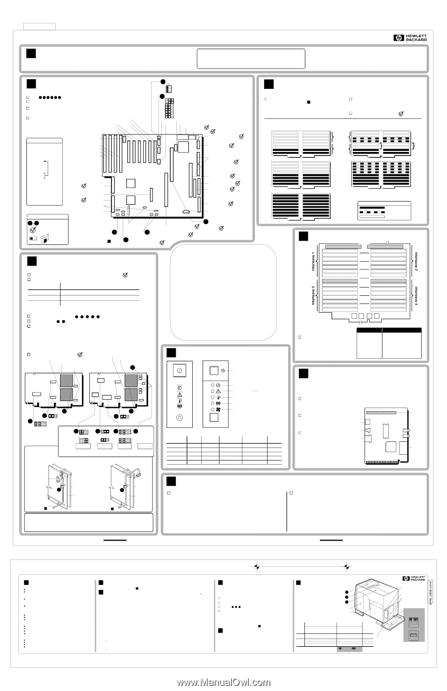
When adding additional memory
capacity, each of four DIMMs must
be placed in each of four interleaves.
The pictureaboveshows an example
of 0.5 GByte installation.
Memor y Capacity
DIMM PopulationInstructions
0.5 GByte
1.0 GByte
1.5 GByte
2.0 GByte
2.5 GByte
3.0 GByte
3.5 GByte
4.0 GByte
Populate J2, J3, J4, J5
add J6, J7, J8, J9
add J10, J11, J12, J13
add J14, J15, J16, J17
add J18, J19, J20, J21
add J22, J23, J24, J25
add J26, J27, J28, J29
add J30, J31, J32, J33
Server Mana gement Board (SMB)
G
Troubleshooting
Note:
the SMB is shipped default with the HP NetServer LXr Pro system and is
located on the System Board in the EISA 4 slot. Never operate thissystem
without the Ser ver Mana gement Boar d.
Fan3
Remote
Assistant
SMB OK
SMBID
50-pin
SMB
Cable
Header
Verify thatthereis a cable
connecting theI
C connection
on the SMB Board tothe I
C
connection, J2G2, on the
System Board.
2
2
Visually check that the Fan3
connector on the SMBBoard
is cabled to Fan3, J2G4 on the
System Board.
Verify thatthe SMB Cableis connected
to the 50-pin header on the SMB Board,
with pin 1 of thecableconnector placed
at the same end as pin 1 of the header
pins.
I
C
2
EXTI
C
2
Power
H
Check the green ONLINE LEDon the frontof
each Power Supply Module (PSM). The unit will
operate with at least two of the three PSMs
ONLINE. Replace any PSMwhich is not
ONLINE. ThePSMs are hot-swappable. It is
notnecessary to shut dow n the server to replace
onefailed PSM.
3
-
Ifall three PSMs will not come ONLINE, the
problemmay be an overload condition. Remove
power connectors toisolate fault.
Check Power Supplies:
Check LED Indicator s (fr om outside of system):
-
Ifoff, check l ine inut ACpower, front and rear power swiches, top cover interlock
switch, and at least two of threepower suppliesare online.
Check ON LED:
1
-
Notallpower supplies are ONLINE. Check the power suppliesas d escribed below.
If green power Supply LED on bottom isOFF:
2
If green Temperature LED is OFF:
4
-
Check fo r a faulty Fan.
If yellow warning LEDis ON:
3
-
Check powersupply LED. If it is OFF, not all powersupplies are O NLINE. Check
the power supplies as described below.
- Ifg reenpower supply LED is O n , check for a faulty fan.
Check the green Power LEDon thefront of
each Power Supply Module(PSM).
2
Remove front panel. Check the bottom
yellow LED (this LED is not visiblewith
thefront panel on):
1
¥Temperature
¥ Power Supply
¥ Fan
Contr ol Panel
F
Reset
Front Bez el
G
Y
G
Y
G
Power Switch
Pow er on
WARNING !
Temperature
Fan
*
*
*
System can l ose a total of one Fan.
If the System loses two Fans
itwill automatically shut down.
Power Supply Status
Reset
Chassis (inside)
LED
Color
System
OK
Temperature
Failure
Power Suppl y
Failure
Fan
Failure
Power
WARNING!
Temperature
Power Supply
Fan
Green
Yellow
Green
Green
Yellow
ON
OFF
ON
ON
OFF
ON
ON
OFF
ON
ON
ON
ON
ON
OFF
OFF
ON
ON
OFF
ON
ON
D4898-80204
DG 002-052256
Key
Check by
visual inspection
Checkwith
Diagnostic Assistant
1
6
System Boar d
B
Boot Order
*
*
*
If " Boot From Embedded
SCSI" isset to"Onboard"
using EISA Configuration
Utility
*
*
Must be enabled using
EISA Configuration
Utility on Navigator CD
CD-ROM
FlexibleDisk
IDE Device
EISA E1
EISA E2
EISA E3
PCI P1
PCI P2
PCI P3
PCI P4
SCSI A
SCSI B
PCI P5
PCI P6
**
1.
2.
3.
4.
5.
6.
7.
8.
9.
10.
11.
12.
13.
14.
Troubleshooting
1
3
4
2
5
Check BIOS version with Diagnostic Assistant
(select "Hardware Inventory").
Check that all p rocessors, SIMMs, and drives
areconnectedandresponding with the
Diagnostic Assistant (select HardwareInventory).
Check operation with Diagnostic Assistant
(select "Quick Tests" then "Run All Tests").
Check
(see board picture)
6
E1
E2
E3
E4
*
SCSI
AIC
7880
SCSI
AIC
7880
Video
Cirrus
GD-5424
3
2
1
Clear CMOSto defaultsettings
Clear Password
Reserved
ON
S6A1 Default Settings
5
Boot from: Recovery / Normal BIOS
Recovery BIOS: Write / Protect
Normal BIOS:Flash Enable / Protect
Floppy-0: 1.44/ Reserved
Floppy-1: 1.44/ Reserved
Video Sleep Reg: 46E8 / 0C3C
Power Control: Disable / Enable
Reserved
J6A1 Default Settings
SCSI Bus B
SCSI Bus A
Unused
Unused
Unused
Fan3: SMBFan Connector, J2G4
(Rotation sense; +12)
Processor Board #1
Must haveeither P rocessor
Board #2 or a Terminator
Board
Control Panel
IDE Disk Drive
(optional)
Flexible Disk Drive
MemoryBoard
Power S upply (20-pin;
interchangeable)
Power S upply
(14-pin)
Video RAM
Monitor
Parallel Port
Serial Ports
Keyboard and Mouse
(interchangeable)
Unused
Unused
HD LEDs from add-on
disk controllers
Real
Time
Clock
I
C for SMB
J2G2
2
4
3
2
1
EISA / ISA Bus:
6
4
Fans 2 & 1 must h ave loopback
connector (p/n 5182-4598)
SMB shipped
default in E4 slot
onall systems
*
Fan4 must have loopback
connector (p/n 5182-4598) or
be connected to Processor
Board as shown on Panel
D
PCI Bus 1: P4
P5
P6
PCI Bus 0: P1
P2
P3
All SIMMs in onebank must be identical in size.
See diagrams below for rules on mixing sizes.
(The memory architecture treats 12 SIMMs asonly
8 SIMMs.)
TwoSIMMsiz es
One SIMM siz e
Bank 2
Bank 1
16
15
1
2
Interleave = 4 (high performance)
Interleave = 2
Interleave = 4 (high performance)
Interleave = 2
Interleave= 4 (high performance)
Must
be
empty
Canuseany two sizes from 32M, 64M, or 128M
32M, 64M, or 128M
All one SIMM size --
Key
SIMM size #1
SIMM size #2
Empty Socket
Audience
This Service Reference Label is for trained service personnel.
Hewlett-Packard Company assumes you are qualified in the
servicing of computer equipment and trained in recognizing
hazards in products with hazardous energy levels.
About This Label
A
Copyright 1997, Hewlett-Packard Company. All rights reserved.
This information issubject to change w ithout notice and ispro
vided w ithout warranty.
A copy ofthislabel can b e printed from the Information Assistant on a current
Navigator CD. Tomaintain safety compliance, do not keepany paper inside the
system cabinet.
Electr ostatic Disc harge
To avoid catastrophic or hidden damage
tocomponents, wear a wrist strap and use a static-dissipative work
surface connected to the chassiswhen handling components. Use
an antistatic service kit, such as 3M 8501/8502/8505 or equivalent.
¨
Operating a CPUchip on an incorrect Processor Module, or at a lower or higherspeed, o r at incorrect
voltage may result in unreliableoperation -- or cause catastrophic orhiddendamagetothechip.
Repairsdue tounauthoriz ed j umper modification oruseofincorrectchip and m odule combinations are not
covered under the warranty. CPU chipssupplied and w arranted by HP for NetServers have an HP label.
Caution:
Processor
D
Processor
Board #2
Two Pr ocessor Boar ds
ToFan 4 on
System Board
i
B
7
Processor
Board #1
One Processor Boar d
Fan Fail
Termination
Plug
Terminator
Board
7
To Fan 4 on
System Board
i
B
Processor
Board #1
5
4
Fan Fail Cable
7
CPU Chip #2
(optional)
CPU Chip #1
Heat Sinks
ITP Scan
Skip/Include
The module in Slot #1 must h ave two chips before adding a m odule in Slot #2. All
moduleslots must be filled. A module with no chipscannot be used a s a Terminator.
Processor
Module Slot #1
Total number ofCPU
chips i n system
2
CPU #1 and CPU #2
TerminatorBoard
3
CPU #1 and CPU #2
CPU #1
4
CPU #1 and CPU #2
CPU #1and CPU #2
Processor
Module Slot #2
Check that system matches one of these configurations:
1
2
Check jumpers and heat sinks
,
,
,
,
using diagram.
3
4
5
6
7
Check fan cables
,
using diagram.
Check Processor Module speed by running Diagnostic Assistant.
Check with Diagnostic Assistant.
All CPUChips and Processor M odules in the system m
ust b e the same speed/cache
combination. Each Processor Module is marked. For example, "200/512K" =
200MHz with 512K cache.
Each CPU Chip speed/cache m odel has a diff
erent power requirement, which requires
a corresponding Processor Module. A module cannot b e converted t o work reliably
with a different chip other than as shown.
If the specific speed/cache combination for the system isnot shown here, refer tothe
Information Assistant on a current Navigator CD.
Troubleshooting
Board Label: "200/1M" or
"200/1M or 200/512K"
200/512K
200/1M
1
2
3
ITP Scan
Skip/Include
Unused
P
P
2
1
P
0
CPU Chip #2
(optional)
CPU Chip #1
Heat Sinks
200/512K
1
CacheSiz e
P
P
2
1
P
P
2
1
2
Active
Heat S i n k
6
Not Used
Connect to
heat sinks
HeatSink
Fan Power
Park("P")positions
havenoeffect.
3
Speed
P
P
2
1
P
0
P
P
2
1
P
0
(200/1MB only)
Troubleshooting
-
If rearpower switch is ON, these LEDs
should all be ON(even if theunit isturned
OFF withthe front panel power button).
- If LEDis ON, check for a faulty fan.
HPNetServer Diagnostic
Assistant:
Run from NavigatorCDor,
Useflexiblediskshipped with systeminpouchundertop cover or,
Download from oneoftheElectronicSupportServices,below.
¨
HPNetServerNavigator CD:
CDisshipped with the system in the Navigator Kit
TheInformationAssistant ontheCDcontains DataSheetsand
completedocumentation and will search, d isplay, andprinton a
NetServersystem oranyWindows
PC.
Acopy of this label can be printed from theInformationAssistanton
a current NavigatorCD. (To maintain safetycompliance,donot
keep anypaperinside thesystem c abinet.)
Subscriptionsareavailable. SeetheInformation Assistant or one
oftheElectronicSupportServices,below, for ordering.
Thecovers,panels, andboardretainers areintegralpartsof th
e system
andmustbeinplace tomaintain dataintegrity under normal lev
els of
electromagnetic noise,staticdischarge, andvibration.
Evenatlowroomtemperatures,allcoversand panels must bein
place
to providecontrolled airflow forsystemreliability
.
All covers,panels, and board retainers (listed above)must be in place when the
systemismovedorshipped.
Shipping theSystem
Theshipping package protects thesystem --including properly installed mass
storagedevices--undernormal shipping conditions. Areplacementshipping
packageisavailableforpurchase; see panel
on thislabel.
(ServiceReference Label isundertopcover)
F or a listofall accessories, u setheInformation Assistant on
a currentNavigator CDordownloadtheHP NetServer Order
Assistantfrom www.hp.com/go/netserver
*
New Quartz Gray color
HPhasofficesinover100 countries.
Check telephone directory.
Electronic Support Services:
Internet W ebPage
Internet FTP
CompuServeLibrary
GO HPPC
HP NetServerBBS 1-208-344-1691
Support
1
Check that each Mass StorageShelfhaseithera drive or a fillerpanel -
- whetherornotthefrontdoorsarein place.
Check foratleast6in. (15cm)of ventilated space attherearofthesystem.
Check that each PowerSupplySlothaseithera Power SupplyModule or
a FillerPanel.
1
2
3
Check that
,
,
,thetwo side covers, and the topcoverarein place-
- whetherthesystemisfree-standing, rack-mounted,or beingshipped.
SupportQuestions:
HP-Authorized Reseller
CompuServe Discussion Forum
GO HPPC
U S / CanadaPhone Support
1-970-635-1000 (Colorado)
Europe Phone Support
(+31-20) 581-3330(Netherlands)
Power SupplyModule
¥ D4292A
PowerSupply
Tested PCI and EISA Cards
2
Product and Part Numbers
3
SystemDimensions
24.6"Hx 16.6"Wx 25.4"D (63cm x 42.5cmx 65cm)
SystemW eight
131- 187lb (59 - 85kg)
Power Availability
790Wcontinuous(410Wcontinuous with one PSM)
Specifications
5
AirConditioningSpecifications
Maximum continuouspower input:1200W (1440W at220V)
Maximum heat output:4100 BTU /hour (4900BTU /hourat220V)
Operating temperaturerange: 41to 95degreesF (5 to35 degrees C)
Data Integrity and System Reliability
4
HP NetServer LX Pro and LXe Pro Product Reference Label
Aug 1, 1997
SCSI Cables
SCSI Array CableKit. Includes A1and2 each
C15-- forconversionfromNon-ArraytoArray.
¥ D4282A
68-pin HD/HD External SCSI Cable
¥ D3636A
68-pin HD/UHD External SCSI Cable
¥ D3637A
Mass Storage Cage Upgrade
LXeProMassStorageCageUpgradeKit
¥ D4927A
MountingT rays
5 1/4" DAT/CD Tray (3-Pack;nofrontpanel)
¥ D2199A
(DrivesmustmeetSCA-23A industry standard;useElectronic
Support Services,Panel 1 ofthislabel,toobtainatestedlist.)
3 1/2" Hot-SwapDrive Tray(single pack)
*
¥ D3349B
*
3 1/2" Non-Hot-SwapDriveTray(3-Pack;front
panel included)
¥ D2198B
Cabinet
¥ 5002-3709
Power SupplyFillerPanel
¥ 5063-8389
MassStorageFillerPanel(Fullheight)
¥ 5182-6795
Bezel FillerLabels(tocoverhingeslotsifdoors
areremoved)
¥ J1455A
Rackmount Kit f orNetServerLX
¥ 5041-5320
Front Door Hinge(4 required)
*
*
3
Filler Panels(required
in any empty PSMslots)
Right-HandMassStorage Area
Power SupplyModule
(PSM)
RemovableSkirt
PSMLED
RemovableSkirt
*
(Seeback ofmachine)
PowerSupply
Mode
OR
PowerSupply
Redundancy
ON
OFF
*
Status LED Switc h
(AffectsonlythePower
SupplyStatusLED on
front panel.)
100mm REF
Cabinet and Redundant
Power System
6
Label Version 5
(D4311-80207, Rev A)
1
FanCoolingDuctCover
3
ProcessorCooling DuctCover
PCI/ EISA BoardRetainer
2
Numberof
Processor
Boards
Mass Storage
Devicesin Right-
Hand Area
System
Configuration
Non-
Redundant
Operation
Redundant
Operation
PowerSupply Modules
Required
Power
Available
LX Pro
yes
1 or2
2
3
790W
no
no
yes
1
2
1 or2
1
2
2
2
3
3
410W
790W
790W
StatusLEDSwitch setting:
OFF
ON
LXe P r o
System
Model
I / O Cards
NetRAIDPCIDualChan. Disk Array Controller
¥ D4963A
PCI10/100VGNIC
¥ J2585B
Remote AssistantCard
¥ D4267C / 68C/69C
PCI10/100TXNIC
¥ J3171A
Processor Upgrades
LX Series6/200 Chip Upgrade Kit
¥ D4867A
LX Series6/200 Dual ProcessorCard
¥ D4866A
LX Series6/166 Chip Upgrade Kit
¥ D4288A
LX Series6/166 Dual ProcessorCard
¥ D4286A
**
**
**
Processor Chipsnotincluded
LX Series6/200 1MB Card(withtwo Chips)
¥ D4966A
Memory
(ECCImplementedwithParity SIMMs)
128MB SIMM(60ns)
¥ D4893A
64MBSIMM (60ns)
¥ D4290A
32MBSIMM (60ns)
¥ D4892A
16MBSIMM (60ns)
¥ D4891A
512MB DIMMKit(four128MBDIMMs)
¥ D4968A
DIMMMemory Board(withfour128MB DIMMs)
¥ D4967A
VideoRAMChip(StandardonModel B)
¥ 5182-9404
Mass Storage
840MB IDE Hard Disk (orderD2198B tray)
¥ D2925A
*
4.2GB Ultra SCSIHot-SwapDiskModule
¥ D3583C
*
2.1GB Ultra SCSIHot-SwapDiskModule
¥ D3582C
*
9.1GB Ultra SCSIHot-SwapDiskModule
¥ D4289A
*
4.2GB 10KUltra SCSIHot-SwapDiskModule
¥ D4903A
Limitations applyto theuseofPCIand EISA
cardsin thissystem. Use oneof the
Electronic SupportServices,panel
ofthislabel,toobtain
a current listoftested cards.
1