HP LH4r HP Netserver LXr Pro8 Technical Reference Label 1 - Page 1
HP LH4r - NetServer - 256 MB RAM Manual
 |
View all HP LH4r manuals
Add to My Manuals
Save this manual to your list of manuals |
Page 1 highlights
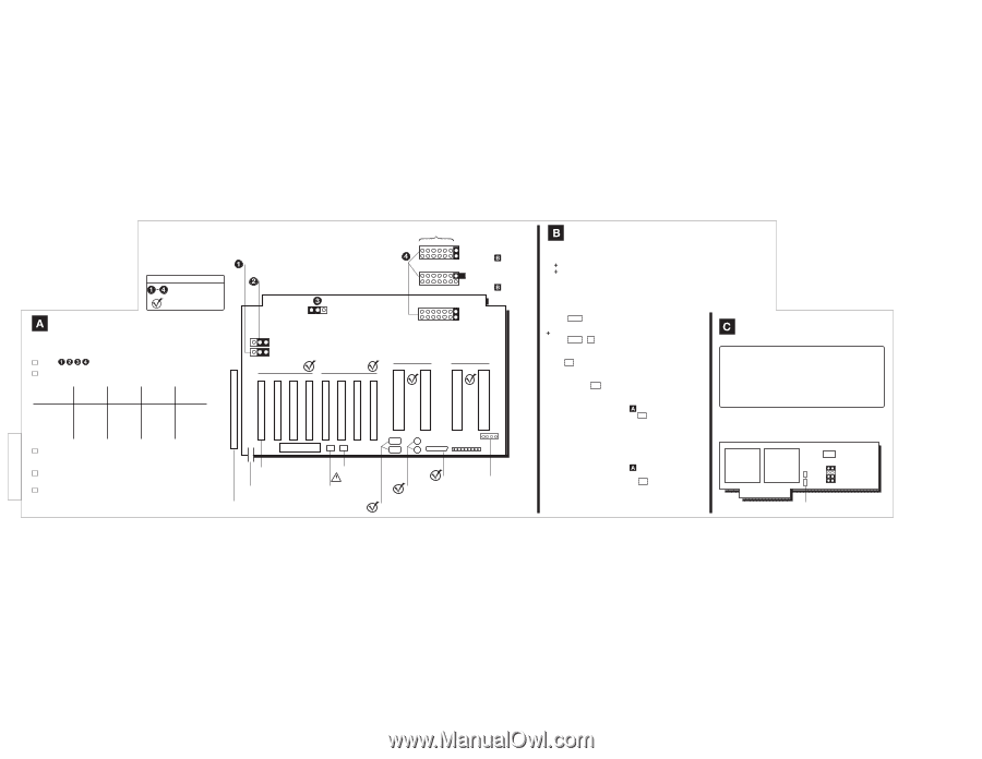
002-52460, Rev B System Board NetServer LXr Pro8 Inside Service Reference Label Key Check by visual inspection Check with Diagnostic Assistant Boot Block BIOS: Flash Enable / Protect Main BIOS: Protect / Flash Enable JP8 (Reserved) Reserved 654 3210 654 3210 Clear CMOS Enable BIOS Recovery Enable (See Panel of this label) Default: Clear CMOS Protect BIOS Recovery Protect (See Panel of this label) 654 3210 CON F Troubleshooting Check (see board picture). Check that system matches one of these configurations. All processor slots must be filled. Total Number of CPU Chips Board in in System Slot A2 Board in Slot A1 Board in Slot B2 Board in Slot B1 2 CPUS Terminator Processor Terminator Terminator 4 CPUS Terminator Processor Terminator Processor 6 CPUS Processor Processor Terminator Processor 8 CPUS Processor Processor Processor Processor Check that all processors, DIMMs, and drives are connected and responding with the Diagnostic Assistant (select Hardware Inventory). Check BIOS version with Diagnostic Assistant (select "Hardware Inventory"). Check operation with Diagnostic Assistant (select "Quick Tests" then "Run All Tests"). JP9 JP10 PCI BUS 0 PCI BUS 1 P1 P2 P3 P4 P5 P6 P7 P8 CPU BUS A A2 A1 CPU BUS B B2 B1 Not Replaceable Boot Status 0 1 2 3 4 5 6 7 Video Card in P1 EXT opening in rear panel Diagnostic Assistant disk pouch Connector Reserved Unused (Reset Switch) Mouse Keyboard Serial B Serial A Printer Unused (Speaker) Firmware Boot Order 1. * CD-ROM (SCSI Address 0) 2. * Flexible Disk 3. Internal SCSI Drives 4. Optional SCSI Extender Drawer 5. PCI P1 • • • • • • 12. PCI P8 * Default: included in boot order. To check or change, press ESC to enter Boot Menu when prompted during Power On Self-Test. Default: included in boot order. To check or change, press Ctrl + C to run SCSI Setup Utility when prompted after memory count stage of boot. ROM Setup Press F2 to enter Setup when prompted during Power On Self-Test. Memory Test Full Test: Press D during memory count stage of boot. Clear CMOS 1 Ensure jumper CONF 0 on System Board is in "Enable" position (see Panel on this label) 2 Power up system while holding F2 down 3 Keyboard LEDs flash when done 4 Power down system 5 Reset jumper to "Protect" position 6 Power up system (takes up to 2 minutes) BIOS Recovery from Boot Block 1 Ensure jumper CONF 0 on System Board is in "Enable" position (see Panel on this label) 2 Put diskette copy of BIOS file in flexible disk drive 3 Power up system while holding F3 down 4 Keyboard LEDs flash when done 5 Power down system 6 Reset jumper to "Protect" position 7 Power up system (takes up to 2 minutes) Processor Caution: Operating a CPU chip on an incorrect Processor Board, or at a lower or higher speed, or at incorrect voltage may result in unreliable operation -- or cause catastrophic or hidden damage to the chip. Repairs due to unauthorized jumper modification or use of incorrect chip and board combinations are not covered under the warranty. CPU chips supplied and warranted by HP for HP NetServers have an HP label. Upper Lower Processor Processor Reserved JP1 JP4 Unused
-
 1
1
 |
 |