HP LH4r HP Netserver LXr Pro8 Technical Reference Label 2
HP LH4r - NetServer - 256 MB RAM Manual
 |
View all HP LH4r manuals
Add to My Manuals
Save this manual to your list of manuals |
HP LH4r manual content summary:
- HP LH4r | HP Netserver LXr Pro8 Technical Reference Label 2 - Page 1
or Download from one of the Electronic Support Services, below. Proactive E-Mail Notification: Sign up at http://www.hp.com/go/netserver. Click on "Service and Support" Electronic Support Services: Internet Web Page http://www.hp.com/go/netserver Internet FTP ftp://ftp.hp.com/pub/servers CompuServe
-
 1
1
 |
 |
002-52459, Rev B
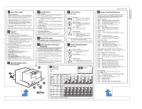
NetServer LXr Pro8 Outside Service Reference Label
NetServer LXr Pro8 Outside Service Reference Label
For a list of all accessories, use the Information Assistant on a current
Navigator CD or download the HP NetServer Order Assistant from
www.hp.com/go/netserver.
For rack configuration and installation
information, download the HP NetServer Rack Assistant.
Product and Part Numbers
8
Audience Assumptions
This Service Reference Label is for trained service personnel.
Hewlett-Packard Company assumes you are qualified in the
servicing of computer equipment and trained in recognizing
hazards in products with hazardous energy levels.
This information is subject to change without notice and is provided
without warranty.
Copyright 1998, Hewlett-Packard Company.
All rights reserved.
About This Label
Electrostatic Discharge
To avoid catastrophic or hidden
damage to components, wear a wrist strap and use a
static-dissipative work surface connected to the chassis
when handling components. Use an antistatic service kit,
such as 3M
8501/8502/8505 or equivalent.
®
HP NetServer Diagnostic Assistant:
Run from Navigator CD, or
Use flexible disk shipped with system in pouch in the satellite, or
Download from one of the Electronic Support Services, below.
®
HP NetServer Navigator CD:
CD is shipped with the system in the Navigator Kit.
The Information Assistant on the CD contains complete
documentation and will search, display, and print on a NetServer
system or any Windows
PC.
A copy of this label can be printed from the Information Assistant
on a current Navigator CD.
(To maintain safety compliance, do
not keep any paper inside the system cabinet.)
Subscriptions are available.
See the Information Assistant or one
of the Electronic Support Services, below, for ordering.
HP has offices in over 100 countries.
Check telephone directory.
Electronic Support Services:
Internet Web Page
Internet FTP
CompuServe Library
GO HPPC
Support Questions:
HP-Authorized Reseller
CompuServe Discussion Forum
GO HPPC
US / Canada Phone Support
1-970-635-1000 (Colorado)
Europe Phone Support
(+31-20) 581-3330 (Netherlands)
Support
Proactive E-Mail Notification:
Sign up at http://www.hp.com/go/netserver.
Click on "Service
and Support"
Uninterruptable Power Supplies (order from APC Corp.)
NS3000RMT3U
NS3000RM
I
3U
208V UPS U.S.
In: L6-20P, Out: 2 L6-20R and 1 L6-30R
230V UPS Europe
In: C20, Out: 1 C19, 8 C13
External Mass Storage
D3636C
D3637C
D4902A
D3583C
D4903A
D4289A
D5039A
SCSI Cable; Std. HD-68 to Std. HD-68, 2.5m
SCSI Cable; Std. HD-68 to Ultra HD-68, 2.5m
Rack Storage/8 Storage Enclosure
4.2GB Hot-Swap Ultra SCSI Disk Module
4.2GB 10,000rpm Hot-Swap Ultra SCSI Disk Module
9.1GB Hot-Swap Ultra SCSI Disk Module
18.2GB Hot-Swap Ultra SCSI Disk Module
I/O Cards
D4943A
D4983B
D5013A
J2585B
NP NetRaid PCI DAC Card
Cable Kit for 3rd connector of D4943A DAC
HP DeskDirect 10/100TX PCI Server LAN Adapter
HP DeskDirect 10/100VG PCI LAN Adapter
Mounting Trays
D2199A
D2198B
5 1/2" DAT / CD Tray (3-pack; no front panel)
3 1/2" Non Hot-Swap Drive Tray (3-pack; incl. front panel)
Internal Mass Storage
D4910A
D4911A
C1555A
4GB wide SCSI HDD with drive mounting tray
9GB wide SCSI HDD with drive mounting tray
DAT Tape, HP Model 24i (order D2199A tray)
Internal Accessories
D5030A
D5026A
D5027A
D5963A
D5972A
D5973A
Processor Board, Dual 200 / 1MB (incl. CPUs)
256MB Memory DIMM Kit (2 ea. 128MB DIMMs)
Second Memory Board (32 DIMM sockets)
Non-DAC Ultra SCSI Extender Drawer, 6-Channel
DAC Cable Extender, 6-Cable
Hot-Swap Kit -- Power Supply and Fan Packs
Power Cords
E7798A
E7804A
E7801A
E7803A
E7799A
E7805A
E7800A
E7806A
D4991A
E7742A
Power Cord, 250 VAC (C20 to C19), 2.5m (std. with system)
Power Cord, 250 VAC (C20 to C19), 4.0m
Power Cord, 240 VAC (L6-20P to C19), 2.5m
Power Cord, 250 VAC (L6-20P to C19), 4.5m
Power Cord, 240 VAC (L6-30P to C19), 2.5m
Power Cord, 240 VAC (L6-30P to C19), 4.5m
Power Cord, 240 VAC (Unterminated to C19), 2.5m
Power Cord, 240 VAC (Unterminated to C19), 4.5m
Y Adapter Power Cord (C14 to 2 C13) (for 2 RS/8s in one rack)
Jumper Power Cord, 2.5m (C14 to C13)
Power Distribution Units (no power cord)
E7670A
E7671A
E7672A
E7666A
10A PDU, 19";
In: C14, Out: 10 C13
16A PDU, 19";
In: C20, Out: 6 C13 and 2 C19
Kit: E7670A and E7671A PDUs plus E7742A Jumper Cord
16A Dual-Input PDU, 56";
In: 2 C20, Out: 2 C19 and 12 C13
(Download HP NetServer Rack Assistant Software for details.
See Panel
on this label.)
D4984A
E7797A
E7723A
D4984-60007
D4950B
C3751B
J1493A
J1497A
J1462A
J1463A
Rack Installation Kit with Extra Hardware and Install Docs
Rack Mounting Hardware Kit (25 ea. 10-32 screws and nuts)
Cable Guide, 24", pkg. of 2
Cable Ties, Hook-and-Loop, 12", pkg. of 5
HP NetServer Keyboard, Mini-DIN
HP Mouse, Mini-DIN
Console Switch 4 port
Console Switch 8 port
Switch / Server Cables, 7 ft, set of 3 for one server
Switch / Server Cables, 12 ft, set of 3 for one server
Rack Accessories
002-52459, Label Version 2
8GB
64
16
Upper
Lower *
7GB
56
16
Upper
Lower *
6GB
48
16
Upper
Lower *
28
24
20
16
12
8
4
0
5GB
40
16
Size
DIMMs
Inter-
leave
Memory
Board
Upper
Lower *
28
24
20
16
12
8
4
0
DIMM Locations
2
4
8
12
16
24
32
4
8
16
8
16
16
16
Size
DIMMs
Inter-
leave
Memory
Board
Upper
Upper
Upper
Upper
Upper
Upper
Upper
256MB
512MB
1GB
1.5GB
2GB
3GB
4GB
Troubleshooting
Check that DIMMs are the correct HP product number.
(See panel
of this label.)
DIMMs supplied and warranted by HP have an
HP label.
Repairs due to the use of non-HP DIMMs are not covered
under the warranty.
31
0
Reserved
Refers to Optional Lower Memory Board
*
Air Conditioning Requirements
Maximum heat output: 3300 BTU/hour
Operating temperature: 41 to 95 degrees F (5 to 35 degrees C)
Operating humidity: 20% to 80% RH noncondensing
Specifications
Space Requirements
System dims: 17.5"H x 19.0"W x 32.1"D (44.5cm x 48.6cm x 81.5cm)
Rack space: 10 EIA units
30" (76cm) beyond rear of HP rack -- no door
Rack clearance: 46" (117cm) beyond rear of HP rack -- door mounted
System weight: 170lb (76kg)
Power Requirements
Voltage and frequency: 200-240VAC 16A single cord input at 47-63Hz
Power availability: 200W continuous to PCI cards and internal drives
Maximum inrush current: 80A for 10ms
Power consumption: 970W typical usage max; 1560W design max
208/240V 60Hz -- NEMA AB1 class 14B 20A for each 16A PDU.
20 Amp branch circuits are recommended, using NEMA L6-20R
receptacles.
• North America
220 / 230 / 240V 50/60Hz -- IEC Type D for 16A circuits for each
16A PDU.
Minimum 16 Amp branch circuits are recommended.
• Outside North America
Tested PCI Cards
Limitations apply to the use of PCI cards in this system.
Refer
to the Configuration Advisor on HP NetServer Navigator CD.
Circuits: Delayed action circuit breaker recommended.
Configurations
use one or two branch circuits per rack.
3
6
4
4
Satellite Disassembly /
Reassembly
Control Panel
Message display on control panel will display fatal errors
for one minute before system shuts down.
Notes:
4-pin connector on rear of Control Panel Board is unused.
Troubleshooting
Check that the Satellite Retention Bracket is in place on
the center rear of the base chassis.
Power On Self-Test
Green during operation = BIOS is running
Green during power up =
has passed;
system is starting to boot
Run Indicator
Green = DC voltages from power supplies OK
Off = System in standby -- press power button.
Check CPU Power Switch on rear of
Docking Station
DC Ouput Indicator
Off = Check AC power to system
Green = AC power input to system OK
AC Input Indicator
Off = Normal operation
Attention Indicator
Component failure -- refer to message
display on Control Panel
Yellow =
Labeling Utility is flashing the light to
identify this server
Flashing Yellow = Hardware Identification and
The covers and panels are integral parts of the system and must
be in place to maintain data integrity under normal levels of
electromagnetic noise, static discharge, and vibration.
Even at low room temperatures, all covers and panels must
be in place to provide controlled airflow for system reliability.
Shipping the System
Check that each Mass Storage Shelf has either a drive or a
filler panel -- whether or not the front door is in place.
Check that the rear panel, two fan packs, and the top cover are
in place -- whether the system is rack-mounted or being shipped.
Data Integrity and System
Reliability
All covers and panels must be in place when the system is moved
or shipped.
The shipping package protects the system -- including properly
installed mass storage devices -- under normal shipping conditions.
Do not ship the system mounted in a rack.
Power Supply Modules
Connector on front of each Power Supply Module is unused.
Notes:
Troubleshooting
Check the Satellite Power Interlock Switch on the left rear
of the base chassis.
AC Input Indicator
Green = AC power input to module OK
Attention Indicator
System is in standby mode or one or more
DC output voltages is out of specification
Yellow =
Off = Normal operation
DC Output Indicator
Off = Check CPU Power Switch on rear of
Docking Station
Green = DC output voltages from module OK
Memory
5
x4