HP ML310 Serial Attached SCSI storage technology, 2nd Edition - Page 10
Cable connectors and receptacles are keyed to correspond to in ports subtractive routing, out ports
 |
View all HP ML310 manuals
Add to My Manuals
Save this manual to your list of manuals |
Page 10 highlights
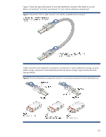
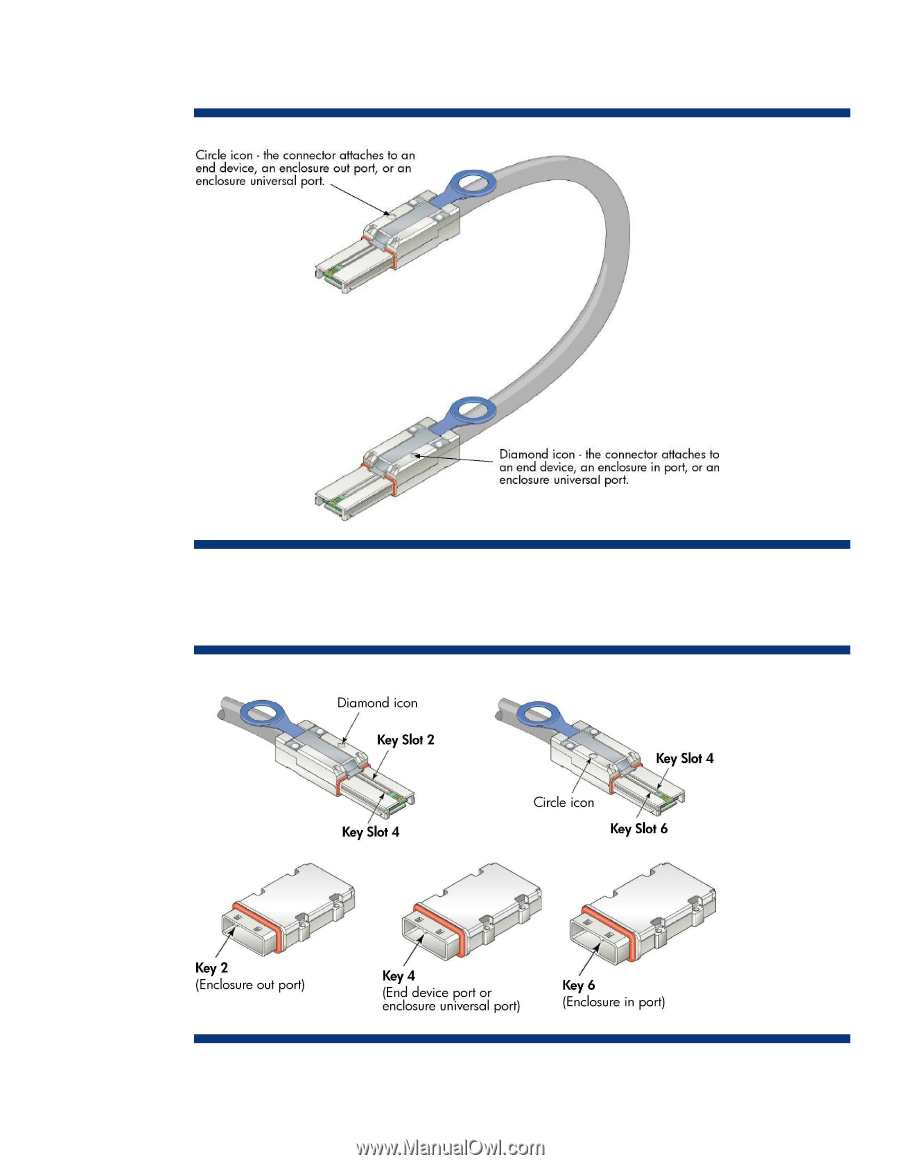
Figure 7 shows the type and location of icons that identify the connectors that attach to an end device, an enclosure ―out‖ port, an enclosure ―in‖ port, and an enclosure universal port. Figure 7. External Mini SAS 4x cable connector icons identify compatible devices and ports. Cable connectors and receptacles are keyed to correspond to in ports (subtractive routing), out ports (table routing), and ports for direct-attached end devices (direct routing). Figure 8 shows the three keying methods. Figure 8. Three key slot positions correspond to enclosure in and out ports and ports for direct-attached devices. 10
-
 1
1 -
2
-
3
-
4
-
 5
5 -
 6
6 -
 7
7 -
 8
8 -
 9
9 -
 10
10 -
 11
11 -
 12
12 -
 13
13 -
 14
14 -
 15
15 -
16
-
17
-
18
 |
 |
10
Figure 7 shows the type and location of icons that identify the connectors that attach to an end
device, an enclosure
―
out
‖
port, an enclosure
―
in
‖
port, and an enclosure universal port.
Figure 7.
External Mini SAS 4x cable connector icons identify compatible devices and ports.
Cable connectors and receptacles are keyed to correspond to in ports (subtractive routing), out ports
(table routing), and ports for direct-attached end devices (direct routing). Figure 8 shows the three
keying methods.
Figure 8
.
Three key slot positions correspond to enclosure in and out ports and ports for direct-attached devices.