HP ML350 HP ProLiant ML350 G6 Server Maintenance and Service Guide - Page 64
Power supply backplane
 |
View all HP ML350 manuals
Add to My Manuals
Save this manual to your list of manuals |
Page 64 highlights
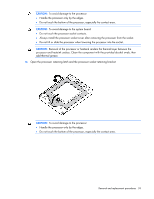
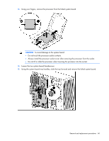
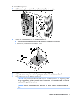
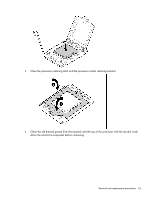
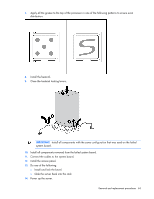
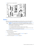
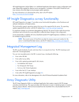
After you replace the system board, you must re-enter the server serial number and the product ID. 1. During the server startup sequence, press the F9 key to access RBSU. 2. Select the System Options menu. 3. Select Serial Number. The following warning is displayed: WARNING! WARNING! WARNING! The serial number is loaded into the system during the manufacturing process and should NOT be modified. This option should only be used by qualified service personnel. This value should always match the serial number sticker located on the chassis. 4. Press the Enter key to clear the warning. 5. Enter the serial number and press the Enter key. 6. Select Product ID. 7. Enter the product ID and press the Enter key. 8. Press the Esc key to close the menu. 9. Press the Esc key to exit RBSU. 10. Press the F10 key to confirm exiting RBSU. The server will automatically reboot. Power supply backplane To remove the component: 1. Power down the server (on page 26). 2. Remove the power supplies ("Hot-plug power supply" on page 36). 3. Do one of the following: o Unlock and remove the bezel ("Front bezel" on page 28). o Extend the server from the rack (on page 25). 4. Remove the access panel ("Access panel" on page 29). 5. Remove the large redundant fan air baffle ("Large redundant fan air baffle" on page 31). 6. Remove the DIMM baffles ("DIMM baffle" on page 32). 7. Remove all fans ("Fan" on page 34). 8. Remove all expansion boards ("Expansion board" on page 44). 9. Remove the system board ("System board" on page 58). For this procedure, removing the processors, heatsinks, DIMMs, and cache module from the system board is not required. 10. Disconnect the cables from the power supply backplane. Removal and replacement procedures 64
-
 1
1 -
2
-
3
-
4
-
5
-
6
-
7
-
8
-
9
-
10
-
11
-
12
-
13
-
14
-
15
-
16
-
17
-
18
-
19
-
20
-
21
-
22
-
23
-
24
-
25
-
26
-
27
-
28
-
29
-
30
-
31
-
32
-
33
-
34
-
35
-
36
-
37
-
38
-
39
-
40
-
41
-
42
-
43
-
44
-
45
-
46
-
47
-
48
-
49
-
50
-
51
-
52
-
53
-
54
-
55
-
56
-
57
-
58
-
 59
59 -
 60
60 -
 61
61 -
 62
62 -
 63
63 -
 64
64 -
 65
65 -
 66
66 -
 67
67 -
 68
68 -
 69
69 -
70
-
71
-
72
-
73
-
74
-
75
-
76
-
77
-
78
-
79
-
80
-
81
-
82
-
83
-
84
-
85
-
86
-
87
-
88
-
89
-
90
-
91
-
92
-
93
-
94
 |
 |