HP Mini 110-3700ca HP Mini and Compaq Mini Getting Started - Windows 7 - Page 19
Bottom
 |
View all HP Mini 110-3700ca manuals
Add to My Manuals
Save this manual to your list of manuals |
Page 19 highlights
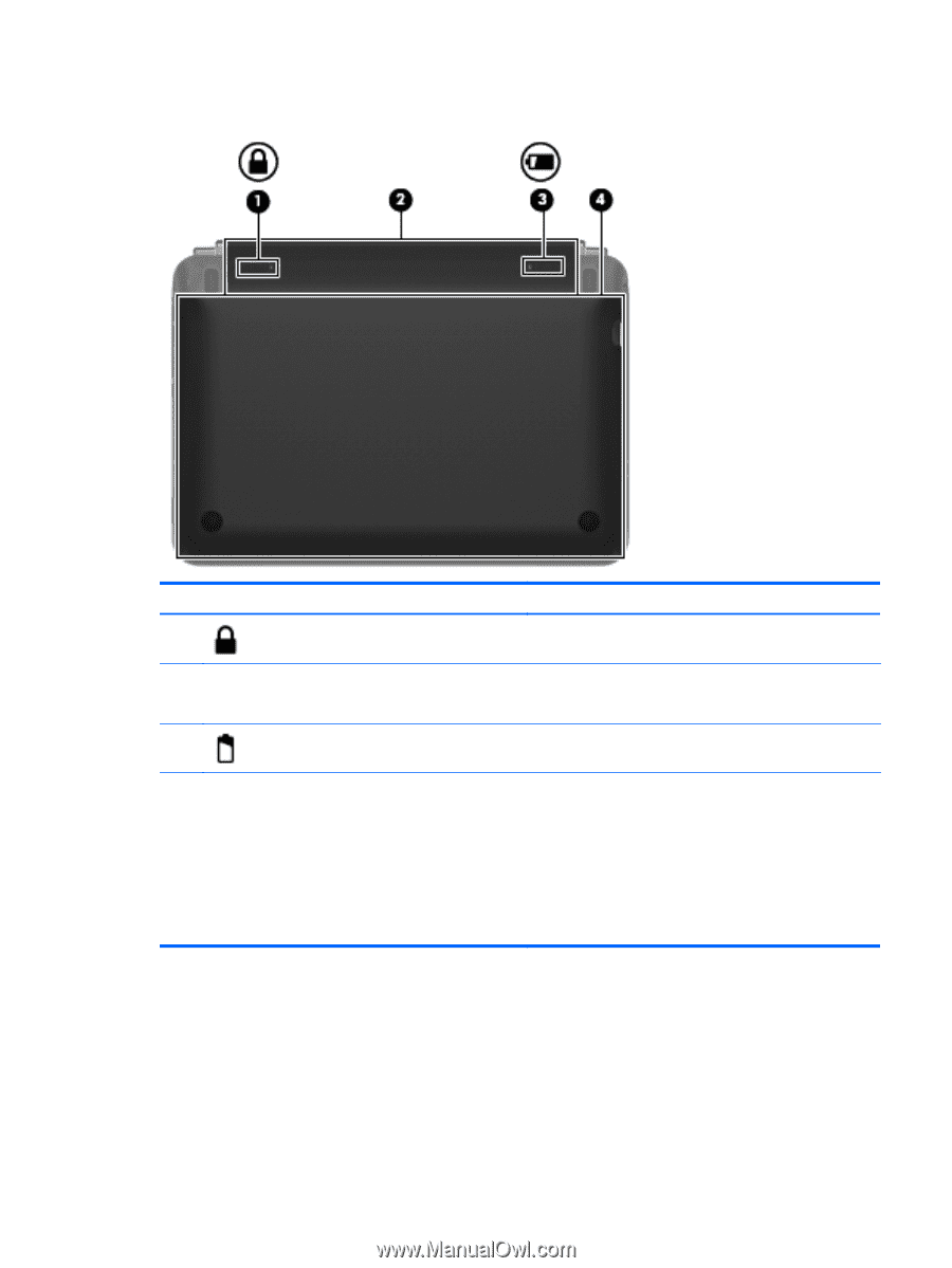
Bottom Component (1) Battery locking latch (2) Battery bay (3) Battery release latch (4) Vanity cover Description Locks the battery into the battery bay. Holds the battery. NOTE: The SIM slot is located under the battery. Releases the battery from the battery bay. Gives access to the hard drive and the memory module and wireless device compartments. CAUTION: To prevent an unresponsive system, replace the wireless module only with a wireless module authorized for use in the computer by the governmental agency that regulates wireless devices in your country or region. If you replace the module and then receive a warning message, remove the module to restore computer functionality, and then contact technical support. Bottom 11
-
 1
1 -
2
-
3
-
4
-
5
-
6
-
7
-
8
-
9
-
10
-
11
-
12
-
13
-
 14
14 -
 15
15 -
 16
16 -
 17
17 -
 18
18 -
 19
19 -
 20
20 -
 21
21 -
 22
22 -
 23
23 -
 24
24 -
25
-
26
-
27
-
28
-
29
-
30
-
31
-
32
-
33
-
34
-
35
-
36
-
37
-
38
-
39
-
40
-
41
-
42
-
43
-
44
-
45
-
46
-
47
-
48
-
49
-
50
-
51
-
52
 |
 |
Bottom
Component
Description
(1)
Battery locking latch
Locks the battery into the battery bay.
(2)
Battery bay
Holds the battery.
NOTE:
The SIM slot is located under the battery.
(3)
Battery release latch
Releases the battery from the battery bay.
(4)
Vanity cover
Gives access to the hard drive and the memory module and
wireless device compartments.
CAUTION:
To prevent an unresponsive system, replace
the wireless module only with a wireless module authorized
for use in the computer by the governmental agency that
regulates wireless devices in your country or region. If you
replace the module and then receive a warning message,
remove the module to restore computer functionality, and
then contact technical support.
Bottom
11