HP Mini 210-1010EB HP Mini 2102, HP Mini 210, and Compaq Mini 210 - Maintenanc - Page 71
CAUTION, Remove the display assembly
 |
View all HP Mini 210-1010EB manuals
Add to My Manuals
Save this manual to your list of manuals |
Page 71 highlights
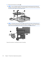
7. Release the wireless antenna cables (2) from the clip built into the base enclosure. CAUTION: Support the display assembly when removing the following screws. Failure to support the display assembly can result in damage to the display assembly and other device components. 8. Remove the two Phillips PM2.0×4.0 screws (1) that secure the display assembly to the base enclosure. 9. Remove the display assembly (2). Reverse this procedure to reassemble and install the display assembly. Component replacement procedures 63
-
 1
1 -
2
-
3
-
4
-
5
-
6
-
7
-
8
-
9
-
10
-
11
-
12
-
13
-
14
-
15
-
16
-
17
-
18
-
19
-
20
-
21
-
22
-
23
-
24
-
25
-
26
-
27
-
28
-
29
-
30
-
31
-
32
-
33
-
34
-
35
-
36
-
37
-
38
-
39
-
40
-
41
-
42
-
43
-
44
-
45
-
46
-
47
-
48
-
49
-
50
-
51
-
52
-
53
-
54
-
55
-
56
-
57
-
58
-
59
-
60
-
61
-
62
-
63
-
64
-
65
-
 66
66 -
 67
67 -
 68
68 -
 69
69 -
 70
70 -
 71
71 -
 72
72 -
 73
73 -
 74
74 -
 75
75 -
 76
76 -
77
-
78
-
79
-
80
-
81
-
82
-
83
-
84
-
85
-
86
-
87
-
88
-
89
-
90
-
91
-
92
-
93
-
94
-
95
-
96
-
97
-
98
-
99
-
100
-
101
-
102
-
103
-
104
-
105
-
106
-
107
-
108
-
109
 |
 |

7.
Release the wireless antenna cables
(2)
from the clip built into the base enclosure.
CAUTION:
Support the display assembly when removing the following screws. Failure to
support the display assembly can result in damage to the display assembly and other device
components.
8.
Remove the two Phillips PM2.0×4.0 screws
(1)
that secure the display assembly to the base
enclosure.
9.
Remove the display assembly
(2)
.
Reverse this procedure to reassemble and install the display assembly.
Component replacement procedures
63