HP Mini 2140 HP 2133 Mini-Note PC and HP 2140 Mini-Note PC - Maintenance and S - Page 68
If you have model 2140, go to step 5. For model 2133, remove the seven Torx8 T8M2.0×6.0
 |
View all HP Mini 2140 manuals
Add to My Manuals
Save this manual to your list of manuals |
Page 68 highlights
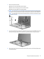
Remove the system board: 1. Disconnect the following cables from the system board: (1) Display panel cable (2) Microphone cable (3) Camera module cable (only on computer models equipped with webcam) 2. Remove the wireless antenna cables from the clips built onto the system board. 3. If you have model 2140, go to step 5. For model 2133, remove the seven Torx8 T8M2.0×6.0 screws (1) that secure the system board and the three system board brackets to the base enclosure. 60 Chapter 4 Removal and replacement procedures
-
 1
1 -
2
-
3
-
4
-
5
-
6
-
7
-
8
-
9
-
10
-
11
-
12
-
13
-
14
-
15
-
16
-
17
-
18
-
19
-
20
-
21
-
22
-
23
-
24
-
25
-
26
-
27
-
28
-
29
-
30
-
31
-
32
-
33
-
34
-
35
-
36
-
37
-
38
-
39
-
40
-
41
-
42
-
43
-
44
-
45
-
46
-
47
-
48
-
49
-
50
-
51
-
52
-
53
-
54
-
55
-
56
-
57
-
58
-
59
-
60
-
61
-
62
-
 63
63 -
 64
64 -
 65
65 -
 66
66 -
 67
67 -
 68
68 -
 69
69 -
 70
70 -
 71
71 -
 72
72 -
 73
73 -
74
-
75
-
76
-
77
-
78
-
79
-
80
-
81
-
82
-
83
-
84
-
85
-
86
-
87
-
88
-
89
-
90
-
91
-
92
-
93
-
94
-
95
-
96
-
97
-
98
-
99
-
100
-
101
-
102
-
103
-
104
-
105
-
106
-
107
-
108
-
109
-
110
-
111
-
112
-
113
-
114
-
115
-
116
-
117
-
118
-
119
-
120
-
121
-
122
-
123
-
124
-
125
-
126
-
127
-
128
-
129
-
130
 |
 |

Remove the system board:
1.
Disconnect the following cables from the system board:
(1)
Display panel cable
(2)
Microphone cable
(3)
Camera module cable (only on computer models equipped with webcam)
2.
Remove the wireless antenna cables from the clips built onto the system board.
3.
If you have model 2140, go to step 5. For model 2133, remove the seven Torx8 T8M2.0×6.0
screws
(1)
that secure the system board and the three system board brackets to the base
enclosure.
60
Chapter 4
Removal and replacement procedures