HP Mini 5103 HP Mini 5103 - Maintenance and Service Guide - Page 76
Remove the display bezel, display bezel until the bezel disengages from the display enclosure.
 |
View all HP Mini 5103 manuals
Add to My Manuals
Save this manual to your list of manuals |
Page 76 highlights
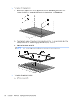
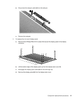
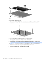
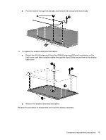
4. To replace the display bezel: a. Remove the 4 Mylar screw covers (1) from the corners of the display bezel, and then remove the 4 2.5×3.0 screws (2) that secure the display bezel to the back cover. b. Flex the inside edges of the left and right sides (1), and then the top and bottom (2) of the display bezel until the bezel disengages from the display enclosure. c. Remove the display bezel (3). NOTE: Tabs on the hinge covers (4) lock to insets on the base enclosure. 5. To replace the webcam module: a. Lift the webcam (1). 68 Chapter 4 Removal and replacement procedures
-
 1
1 -
2
-
3
-
4
-
5
-
6
-
7
-
8
-
9
-
10
-
11
-
12
-
13
-
14
-
15
-
16
-
17
-
18
-
19
-
20
-
21
-
22
-
23
-
24
-
25
-
26
-
27
-
28
-
29
-
30
-
31
-
32
-
33
-
34
-
35
-
36
-
37
-
38
-
39
-
40
-
41
-
42
-
43
-
44
-
45
-
46
-
47
-
48
-
49
-
50
-
51
-
52
-
53
-
54
-
55
-
56
-
57
-
58
-
59
-
60
-
61
-
62
-
63
-
64
-
65
-
66
-
67
-
68
-
69
-
70
-
 71
71 -
 72
72 -
 73
73 -
 74
74 -
 75
75 -
 76
76 -
 77
77 -
 78
78 -
 79
79 -
 80
80 -
 81
81 -
82
-
83
-
84
-
85
-
86
-
87
-
88
-
89
-
90
-
91
-
92
-
93
-
94
-
95
-
96
-
97
-
98
-
99
-
100
-
101
-
102
-
103
-
104
-
105
-
106
-
107
-
108
-
109
-
110
-
111
-
112
-
113
-
114
-
115
-
116
-
117
-
118
-
119
-
120
-
121
-
122
-
123
-
124
-
125
-
126
-
127
-
128
-
129
-
130
-
131
-
132
-
133
-
134
-
135
-
136
-
137
-
138
-
139
 |
 |
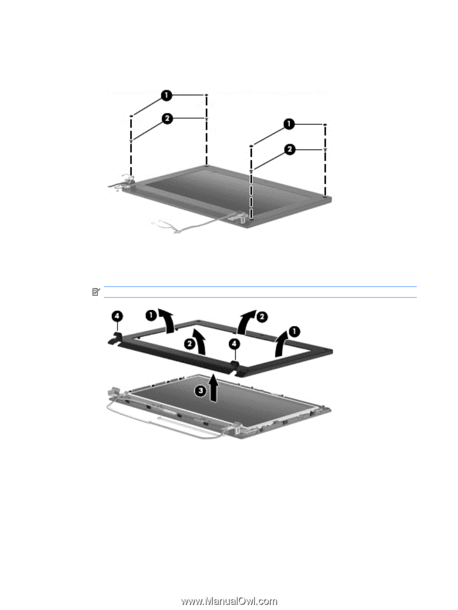
4.
To replace the display bezel:
a.
Remove the 4 Mylar screw covers
(1)
from the corners of the display bezel, and then
remove the 4 2.5×3.0 screws
(2)
that secure the display bezel to the back cover.
b.
Flex the inside edges of the left and right sides
(1)
, and then the top and bottom
(2)
of the
display bezel until the bezel disengages from the display enclosure.
c.
Remove the display bezel
(3)
.
NOTE:
Tabs on the hinge covers
(4)
lock to insets on the base enclosure.
5.
To replace the webcam module:
a.
Lift the webcam
(1)
.
68
Chapter 4
Removal and replacement procedures