HP Mini CQ10-100 Compaq Mini CQ10 Notebook PC and Compaq Mini 102 Notebook PC - Page 72
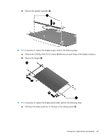
Remove the 4 Phillips PM2.5×4.0 screws, Remove the display assembly
 |
View all HP Mini CQ10-100 manuals
Add to My Manuals
Save this manual to your list of manuals |
Page 72 highlights
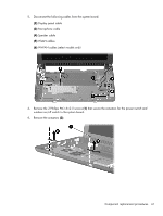
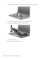
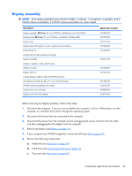
Remove the display assembly: 1. Release the tape securing the WWAN antennas (1). 2. Disconnect the following cables from the system board: (2) Display panel cable (3) Microphone cable (4) Speaker cable (5) WLAN cables (6) WWAN cables (select models only) CAUTION: Support the display assembly when removing the following screws. Failure to support the display assembly can result in damage to the display assembly and other computer components. 3. Remove the 4 Phillips PM2.5×4.0 screws (1) that secure the display assembly to the computer. NOTE: One screw on the left hinge (2) also secures the display panel cable ground strap. 64 Chapter 4 Removal and replacement procedures
-
 1
1 -
2
-
3
-
4
-
5
-
6
-
7
-
8
-
9
-
10
-
11
-
12
-
13
-
14
-
15
-
16
-
17
-
18
-
19
-
20
-
21
-
22
-
23
-
24
-
25
-
26
-
27
-
28
-
29
-
30
-
31
-
32
-
33
-
34
-
35
-
36
-
37
-
38
-
39
-
40
-
41
-
42
-
43
-
44
-
45
-
46
-
47
-
48
-
49
-
50
-
51
-
52
-
53
-
54
-
55
-
56
-
57
-
58
-
59
-
60
-
61
-
62
-
63
-
64
-
65
-
66
-
 67
67 -
 68
68 -
 69
69 -
 70
70 -
 71
71 -
 72
72 -
 73
73 -
 74
74 -
 75
75 -
 76
76 -
 77
77 -
78
-
79
-
80
-
81
-
82
-
83
-
84
-
85
-
86
-
87
-
88
-
89
-
90
-
91
-
92
-
93
-
94
-
95
-
96
-
97
-
98
-
99
-
100
-
101
-
102
-
103
-
104
-
105
-
106
-
107
-
108
-
109
-
110
-
111
-
112
-
113
-
114
-
115
-
116
-
117
-
118
-
119
 |
 |

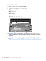
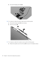
Remove the display assembly:
1.
Release the tape securing the WWAN antennas
(1)
.
2.
Disconnect the following cables from the system board:
(2)
Display panel cable
(3)
Microphone cable
(4)
Speaker cable
(5)
WLAN cables
(6)
WWAN cables (select models only)
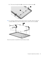
CAUTION:
Support the display assembly when removing the following screws. Failure to
support the display assembly can result in damage to the display assembly and other computer
components.
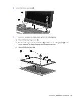
3.
Remove the 4 Phillips PM2.5×4.0 screws
(1)
that secure the display assembly to the computer.
NOTE:
One screw on the left hinge
(2)
also secures the display panel cable ground strap.
64
Chapter 4
Removal and replacement procedures