HP Model 712/80 hp 9000 series 700 model 712 technical reference manual (a2615 - Page 32
Interface Connector Pinouts, Table 2-8. Teleshare Slot Connector Pinouts
 |
View all HP Model 712/80 manuals
Add to My Manuals
Save this manual to your list of manuals |
Page 32 highlights
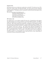
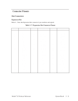
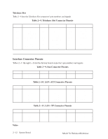
Teleshare Slot Table 2-8 lists the Teleshare Slot connector's pin numbers and signals. Table 2-8. Teleshare Slot Connector Pinouts Pin No. A1 A2 A3 A4 A5 A6 A7 A8 A9 A10 Signal VDD p12V AUD_RESET_L Ground AUD_SDOUT Ground AUD_SCLK VDD DATA_ENABLE Ground Pin No. A11 A12 A13 A14 A15 B1 B2 B3 B4 B5 Signal CFSYNC Ground CSDOUT Ground VDD PWR_RST_L AUD_ALEX_HER VDD AUD_DNC Ground Pin No. B6 B7 B8 B9 B10 B11 B12 B13 B14 B15 Signal AUD_SDIN Ground AUD_FSYNC Ground TSPARE VDD CSCLK Ground CSDIN Ground Interface Connector Pinouts Tables 2-9 through 1-16 list the System board connector's pin numbers and signals. Table 2-9. Fan Connector Pinouts Pin No. 1 2 Signal FAN+ FAN- Pin No. 3 4 Signal THERM- THERM+ Pin No. Table 2-10. LAN-AUI Connector Pinouts Signal Pin No. 1 2 3 4 5 6 Signal CI-S CI-A DO-A DI-S DI-A VC Pin No. 7 8 9 10 11 12 Signal CO-A CO-S CI-B DO-B DO-S DI-B Pin No. 13 14 15 16 17 Table 2-11. LAN-TP Connector Pinouts Signal VP VS CO-B Ground (Shield) Ground (Shield) Pin No. 1 2 3 4 Video Signal TD+ TD- RD+ Unused Pin No. 5 6 7 8 Signal Unused RD- Unused Unused Pin No. 9 10 Signal Ground (Shield) Ground (Shield) 2-12 System Board Model 712 Technical Reference
-
 1
1 -
2
-
3
-
4
-
5
-
6
-
7
-
8
-
9
-
10
-
11
-
12
-
13
-
14
-
15
-
16
-
17
-
18
-
19
-
20
-
21
-
22
-
23
-
24
-
25
-
26
-
 27
27 -
 28
28 -
 29
29 -
 30
30 -
 31
31 -
 32
32 -
 33
33 -
 34
34 -
 35
35 -
 36
36 -
 37
37 -
38
-
39
-
40
-
41
-
42
-
43
-
44
-
45
-
46
-
47
-
48
-
49
-
50
-
51
-
52
-
53
-
54
-
55
-
56
-
57
-
58
-
59
-
60
-
61
-
62
-
63
-
64
-
65
-
66
-
67
-
68
-
69
-
70
-
71
-
72
-
73
-
74
-
75
-
76
-
77
-
78
-
79
-
80
-
81
-
82
-
83
-
84
-
85
-
86
-
87
-
88
-
89
-
90
-
91
-
92
-
93
-
94
 |
 |
