HP Model 715/50 hp 9000 series 700 model 715 workstations service handbook (a2 - Page 48
Changing the Built-In Graphics Configuration, Switches Models 715/C, 715/33, 715/50, 715/75
 |
View all HP Model 715/50 manuals
Add to My Manuals
Save this manual to your list of manuals |
Page 48 highlights
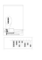
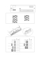
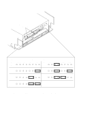
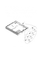
Changing the Built-In Graphics Configuration Switches (Models 715/C, 715/33, 715/50, 715/75) Figure 3-16 shows the built-in graphics configuration switch settings. Set the switches according to the type of monitor that is connected to the system unit's built- in graphics connector. First open the system unit, as described in Chapter 5, to allow a clear view of the switches. Use a small probe to set the switches through the access hole on the rear of the system unit. NOTICE: The built-in graphics configuration switches have no affect on the operation of the optional CRX graphics unit (if installed). Access Hole 20" Color 17" Color 19" Grayscale 15" Color (Model 715/33 only) Figure 3-16. Changing the Graphics Configuration Switches Configuration 3-17
-
 1
1 -
2
-
3
-
4
-
5
-
6
-
7
-
8
-
9
-
10
-
11
-
12
-
13
-
14
-
15
-
16
-
17
-
18
-
19
-
20
-
21
-
22
-
23
-
24
-
25
-
26
-
27
-
28
-
29
-
30
-
31
-
32
-
33
-
34
-
35
-
36
-
37
-
38
-
39
-
40
-
41
-
42
-
 43
43 -
 44
44 -
 45
45 -
 46
46 -
 47
47 -
 48
48 -
 49
49 -
 50
50 -
 51
51 -
 52
52 -
 53
53 -
54
-
55
-
56
-
57
-
58
-
59
-
60
-
61
-
62
-
63
-
64
-
65
-
66
-
67
-
68
-
69
-
70
-
71
-
72
-
73
-
74
-
75
-
76
-
77
-
78
-
79
-
80
-
81
-
82
-
83
-
84
-
85
-
86
-
87
-
88
-
89
-
90
-
91
-
92
-
93
-
94
-
95
-
96
-
97
-
98
-
99
-
100
-
101
-
102
-
103
-
104
-
105
-
106
-
107
-
108
-
109
-
110
-
111
-
112
-
113
-
114
-
115
-
116
-
117
-
118
-
119
-
120
-
121
-
122
-
123
-
124
-
125
-
126
-
127
-
128
-
129
-
130
-
131
-
132
-
133
-
134
-
135
-
136
-
137
-
138
-
139
-
140
-
141
-
142
-
143
-
144
-
145
-
146
-
147
-
148
-
149
-
150
 |
 |
