HP Nx7400 HP Compaq nx7300 and nx7400 Notebook PC Maintenance and Service Guid - Page 119
Lift the right side of the heat sink, from the processor.
 |
UPC - 882780786653
View all HP Nx7400 manuals
Add to My Manuals
Save this manual to your list of manuals |
Page 119 highlights
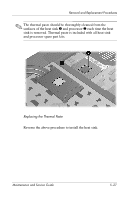
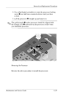
Removal and Replacement Procedures ✎ The following s should be loosened and installed in the 1, 2, 3, 4 sequence stamped on the heat sink. 4. Loosen the four Phillips PM2.0×8.0 shoulder screws 1 that secure the heat sink to the computer. ✎ Due to the adhesive quality of the thermal paste located between the heat sink and processor, it may be necessary to move the heat sink from side to side to detach the heat sink from the processor. 5. Lift the right side of the heat sink 2 until it disengages from the processor. 6. Slide the heat sink 3 to the right and remove it. Removing the Heat Sink 5-26 Maintenance and Service Guide
-
 1
1 -
2
-
3
-
4
-
5
-
6
-
7
-
8
-
9
-
10
-
11
-
12
-
13
-
14
-
15
-
16
-
17
-
18
-
19
-
20
-
21
-
22
-
23
-
24
-
25
-
26
-
27
-
28
-
29
-
30
-
31
-
32
-
33
-
34
-
35
-
36
-
37
-
38
-
39
-
40
-
41
-
42
-
43
-
44
-
45
-
46
-
47
-
48
-
49
-
50
-
51
-
52
-
53
-
54
-
55
-
56
-
57
-
58
-
59
-
60
-
61
-
62
-
63
-
64
-
65
-
66
-
67
-
68
-
69
-
70
-
71
-
72
-
73
-
74
-
75
-
76
-
77
-
78
-
79
-
80
-
81
-
82
-
83
-
84
-
85
-
86
-
87
-
88
-
89
-
90
-
91
-
92
-
93
-
94
-
95
-
96
-
97
-
98
-
99
-
100
-
101
-
102
-
103
-
104
-
105
-
106
-
107
-
108
-
109
-
110
-
111
-
112
-
113
-
 114
114 -
 115
115 -
 116
116 -
 117
117 -
 118
118 -
 119
119 -
 120
120 -
 121
121 -
 122
122 -
 123
123 -
 124
124 -
125
-
126
-
127
-
128
-
129
-
130
-
131
-
132
-
133
-
134
-
135
-
136
-
137
-
138
-
139
-
140
-
141
-
142
-
143
-
144
-
145
-
146
-
147
-
148
-
149
-
150
-
151
-
152
-
153
-
154
-
155
-
156
-
157
-
158
-
159
-
160
-
161
-
162
-
163
-
164
-
165
-
166
-
167
-
168
-
169
-
170
-
171
-
172
-
173
-
174
-
175
-
176
-
177
-
178
-
179
-
180
-
181
-
182
-
183
-
184
-
185
-
186
-
187
-
188
-
189
-
190
-
191
-
192
-
193
-
194
-
195
-
196
-
197
-
198
-
199
-
200
-
201
-
202
-
203
-
204
-
205
-
206
-
207
-
208
-
209
-
210
-
211
-
212
-
213
-
214
-
215
-
216
-
217
-
218
-
219
-
220
-
221
-
222
-
223
-
224
-
225
-
226
-
227
-
228
-
229
-
230
-
231
-
232
-
233
-
234
-
235
-
236
-
237
-
238
-
239
-
240
-
241
-
242
 |
 |

5–26
Maintenance and Service Guide
Removal and Replacement Procedures
✎
The following s should be loosened and installed in the
1, 2, 3, 4 sequence stamped on the heat sink.
4. Loosen the four Phillips PM2.0×8.0 shoulder screws
1
that
secure the heat sink to the computer.
✎
Due to the adhesive quality of the thermal paste located
between the heat sink and processor, it may be necessary to
move the heat sink from side to side to detach the heat sink
from the processor.
5. Lift the right side of the heat sink
2
until it disengages from
the processor.
6. Slide the heat sink
3
to the right and remove it.
Removing the Heat Sink