HP P2000 HP StorageWorks Controller Enclosure Chassis Replacement Instructions - Page 1
HP P2000 Manual
 |
View all HP P2000 manuals
Add to My Manuals
Save this manual to your list of manuals |
Page 1 highlights
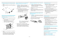
HP Chassis Replacement Instructions This document details procedures for replacing a failed controller enclosure or drive enclosure chassis. When replacing a chassis, all modular components are removed from the failed chassis and then installed in the replacement chassis. About This Document • Illustrations in this document may show modules or a chassis that differ from your devices. • The Storage Management Utility (SMU) and the Command Line Interface (CLI) can be used to manage the storage. Tasks in this document demonstrate using the SMU. • For the latest product documentation, see the HP website at http://www.hp.com/support/manuals. Under the storage banner, navigate to the page for your device. • Warranties for HP products and services are set forth in the express warranty statements accompanying such products and services. Nothing herein should be construed as constituting an additional warranty. HP shall not be liable for technical or editorial errors or omissions contained herein. To obtain a copy of the warranty for this product, see the warranty information website: http://www.hp.com/ go/storagewarranty. Before you begin Observe the following: CAUTION: Parts can be damaged by electrostatic discharge; use proper anti-static protection. Keep parts in electrostatic containers until needed and ensure you are properly grounded when touching static-sensitive components. Procedural overview Replacing a failed chassis includes the following key steps: 1. Removing drive and drive blank modules from the failed chassis. 2. Removing the failed chassis from the rack. 3. Moving side brackets to the replacement chassis. 4. Moving power and cooling, controller, I/O, or air management modules to the replacement chassis. 5. Installing the replacement chassis in the rack. 6. Installing drive or drive blank modules in the replacement chassis. Preparing for the replacement 1. If the controller enclosure or drive enclosure chassis is operational, do the following: a. Stop all I/O to the storage system that includes the failed chassis. b. Shutdown all array controllers in the system. To shutdown a controller using the SMU, select the array in the navigation tree and then select Tools>Shutdown or Restart Controller. After the controller is shut down, the blue "OK to Remove" LED on the controller illuminates. 2. Turn off power and cooling module switches (if present). 3. Make sure all cables are clearly labelled and then disconnect all cables, including power cords, from the modules. Removing drive and drive blank modules from the failed chassis CAUTION: • These procedures require that all drives be removed from the failed chassis. • Because drives are heavy, HP recommends removing drives prior to moving the chassis. If this is not possible, two or more people are required. • Remove drives only after confirming that all internal movement has halted. • As a best practice, remove drive and drive blank modules in bay-number sequence and organize them on your work surface in bay-number sequence. This helps ensure that you reinstall the modules in the same bay number from which they were removed. 1. Press and slide the release latch button to release the latch handle (1). 2. Rotate out the latch handle to disengage the module from the internal connector (2). 3. Pull the module straight out of the chassis (3). © Copyright 2009, 2011 Hewlett-Packard Development Company, L.P. Printed in the US Do the following before beginning these procedures: • Schedule a maintenance window that will include time for shutdown, sixty minutes of replacement work, and restart. • Verify that there is a known, good backup of the system. • Record system settings. • Label all cables. • Prepare a large, stable work surface. Part number: 590358-002 April 2011 edition: 2 *590358-002* IMPORTANT: Use caution when handling Fibre Channel cables: • Touching the end of a Fibre Channel cable either damages the cable or causes performance Removing the failed chassis from the rack problems, including intermittent difficulties accessing the storage. CAUTION: Because drives are heavy, HP • When a Fibre Channel cable or port is not recommends removing drives prior to moving the connected, install protective covers on the ends chassis. If this is not possible, two or more people are of the cable or in the device port. required to lift the chassis. 1. Remove the ear bezels by grasping each bezel firmly and pulling until the bezel separates from the ball nuts on the chassis ear. 2. Remove retaining screws securing the front and rear of the chassis to the rack and rails. 3. Remove the chassis from the rack. 4. Place the failed chassis on the work surface near the replacement chassis. Page 1
-
 1
1 -
 2
2
 |
 |