HP P6000 HP Controller Enclosure Battery Replacement Instructions (593090-001, - Page 1
HP P6000 Manual
 |
View all HP P6000 manuals
Add to My Manuals
Save this manual to your list of manuals |
Page 1 highlights
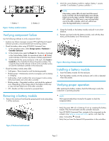
HP Controller Enclosure Battery Replacement Instructions © Copyright 2009 Hewlett-Packard Development Company, L.P. Second edition: May 2011 The information in this document is subject to change without notice. Printed in Puerto Rico www.hp.com About this document For the latest documentation, go to http://www.hp.com/support/ manuals, and select your product. The information contained herein is subject to change without notice. The only warranties for HP products and services are set forth in the express warranty statements accompanying such products and services. Nothing herein should be construed as constituting an additional warranty. HP shall not be liable for technical or editorial errors or omissions contained herein. WARRANTY STATEMENT: To obtain a copy of the warranty for this product, see the warranty information website: http://www.hp.com/go/storagewarranty Before you begin Observe the following precautions when replacing the battery module. CAUTION: Removing a battery module significantly changes the air flow within the enclosure. Both modules must be installed for the enclosure to cool properly. If a single battery module fails, leave it in place in the enclosure until a new module is available to install. • Port-colored (purple) handles on components like the battery module means the component is hot-swappable. The battery can be removed and replaced without having to power the system down. • There are two battery modules under the bezel on the front of the controller enclosure. See Figure 1 for the locations. Each battery provides power to the controller directly across from it in the enclosure. Battery 1 (B1) provides power to controller 2 (C2) and battery 2 (B2) provides power to controller 1 (C1). • Your controller enclosure model may vary slightly from what is illustrated in this document. *593090-001* Page 1
-
 1
1 -
 2
2
 |
 |