HP P6000 HP Controller Enclosure Midplane Replacement Instructions (593095-001 - Page 5
Verifying proper operation - command view
 |
View all HP P6000 manuals
Add to My Manuals
Save this manual to your list of manuals |
Page 5 highlights
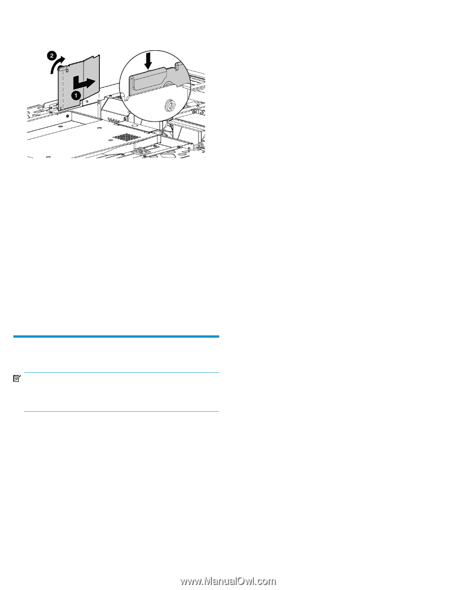
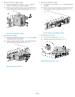
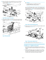
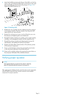
3. Attach both baffles by placing the flange of the baffle over the thin chassis wall, and sliding the baffle down and forward so the small tab on the baffle goes into the slot in the chassis (1, Figure 12). Tighten the baffle thumbscrew (2). Figure 12 Attaching baffle . 4. Reattach the riser assembly onto the midplane board by seating it on its mating connector. Plug the connector from the power UID cable into the riser card connector. 5. Reattach the enclosure top access cover by sliding the cover onto the enclosure and tightening the cover thumbscrew. 6. Reinstall the battery modules, fan modules, power supply modules, controllers, and management module into their respective slots. 7. Reinstall the enclosure into the rack (observing the two-man lift requirements), and reattach the enclosure front bezel. 8. Reattach all cables (Fibre Channel and/or SAS, Ethernet, power) to the enclosure components. 9. Power up attached disk enclosures by pressing the power button on the rear power UID bezel of each disk enclosure. 10. Power up the controller enclosure by pressing the power button on the rear power UID bezel of the controller enclosure. Verifying proper operation NOTE: Wait approximately five minutes for the system to check the status of components after the enclosure is powered on. After replacing the midplane board, check the status of all components with HP P6000 Command View and the indicators of all installed components for proper operation. Page 5
-
 1
1 -
 2
2 -
 3
3 -
 4
4 -
 5
5
 |
 |