HP P6000 HP StorageWorks disk enclosure fan interconnect board replacement ins - Page 2
Verifying component failure, Removing a fan interconnect board, No AC power - hard disk failure warning
 |
View all HP P6000 manuals
Add to My Manuals
Save this manual to your list of manuals |
Page 2 highlights
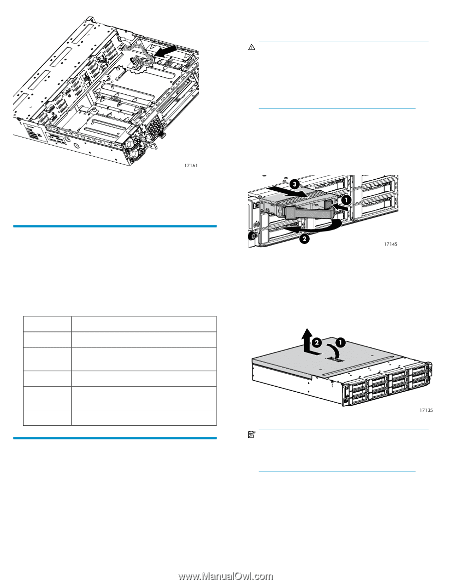
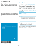
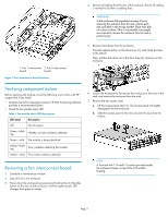
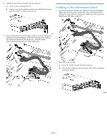
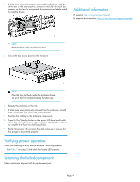
4. Remove all cabling from the rear of the enclosure. Ensure all cabling is marked to facilitate re-cabling later. WARNING! A disk enclosure fully populated is heavy. Prior to removing the enclosure from the rack, remove each disk and label it with its bay number. Place each disk on a clean surface. If this is not possible, two people are required to remove the enclosure from the rack to prevent injury. 1. Fan 1 interconnect 2. Fan 2 interconnect board board Figure 1 Fan interconnect board locations 5. Remove hard drives from the enclosure. Press the release button on the drive lever (1), and rotate the lever to the left (2). Then, pull the disk drive out of the drive bays (3), leaving it in the enclosure. Verifying component failure Before replacing the module, check the following and confirm with HP support that it has failed: • Analyze any failure messages received. HP fault monitoring software provides a recommended action. • Check the fan module status LED. Table 1 Fan module status LED descriptions LED status Description Off No AC power Green-blinking Healthy, no fault conditions detected Green-solid The module is being identified Amber-blinking Error, problems detecting the module. Amber-solid Error, fault conditions detected Removing a fan interconnect board 1. Schedule a maintenance window. 2. Stop all I/O to the enclosure. 3. Power down the enclosure by pressing and holding the On/Standby button on the rear of disk enclosure, until the system power LED changes from green to amber. 6. Loosen the thumbscrews that secure the enclosure to the front of the rack, and remove the enclosure from the rack. 7. Remove the top access cover. a. Lift the access panel latch (1). The access panel will slightly disengage from the enclosure. b. Slide the access panel to the rear (2) and lift away from the chassis. NOTE: A Torx tool with T-10 and T-15 ends is provided inside the enclosure chassis, on top of the I/O module housing. Page 2
-
 1
1 -
 2
2 -
 3
3 -
 4
4
 |
 |