HP P6300 HP Controller Enclosure Riser Assembly Replacement Instructions (5930 - Page 3
Installing a riser assembly, Verifying proper operation - cabling
 |
View all HP P6300 manuals
Add to My Manuals
Save this manual to your list of manuals |
Page 3 highlights
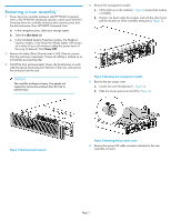
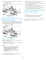
7. Pull up on the riser assembly to unseat it from its mating connector on the midplane board (Figure 4). 5. Reinstall the enclosure into the rack (observing the two-man lift requirements), and reattach the enclosure front bezel. 6. Reattach all cables (Fibre Channel and/or SAS, Ethernet, power) cables to the enclosure components. 7. Power up attached disk enclosures by pressing the power button on the rear power UID bezel of each disk enclosure. 8. Power up the controller enclosure by pressing the power button on the rear power UID bezel of the controller enclosure. Verifying proper operation Figure 4 Removing the riser assembly . Installing a riser assembly 1. Align the connector on the bottom of the replacement riser assembly with its mating connector on the midplane board and press down to seat the connectors (Figure 5). The tabs on the metal riser cover insert into the slots in the enclosure. NOTE: Wait approximately five minutes for the system to check the status of components after the enclosure is powered on. After replacing the riser assembly, verify that the green LEDs are lit on the management module and the power UID. Figure 5 Attaching the riser assembly . 2. Attach the cable connector from the power UID assembly into the connector on the riser assembly. 3. Reattach the top access cover by sliding the cover onto the enclosure and tightening the cover thumbscrew. NOTE: The top access cover helps properly align the riser assembly by pressing down on the raised portion of the riser assembly bracket. Do not install the management module until the top access cover has been attached to the enclosure, or you may have alignment difficulties. 4. Insert the management module into the enclosure, and push it in until it clicks to indicate it is fully seated. Page 3
-
 1
1 -
 2
2 -
 3
3
 |
 |
