HP Pavilion 13-u100 Maintenance and Service Guide - Page 63
Remove the Phillips PM2.0×2.3 screw, that secures the WLAN module to the system board.
 |
View all HP Pavilion 13-u100 manuals
Add to My Manuals
Save this manual to your list of manuals |
Page 63 highlights
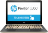
a. Battery (see Battery on page 42). b. USB port shield (see USB port shield on page 50). c. System board (see System board on page 51). Remove the WLAN module: 1. Turn the system board upside down with the front toward you. 2. Remove the Phillips PM2.0×2.3 screw (1) that secures the WLAN module to the system board. (The WLAN module tilts up (2).) 3. Remove the WLAN module (3) by pulling the module away from the slot at an angle. Reverse this procedure to install the WLAN module. Component replacement procedures 55
-
 1
1 -
2
-
3
-
4
-
5
-
6
-
7
-
8
-
9
-
10
-
11
-
12
-
13
-
14
-
15
-
16
-
17
-
18
-
19
-
20
-
21
-
22
-
23
-
24
-
25
-
26
-
27
-
28
-
29
-
30
-
31
-
32
-
33
-
34
-
35
-
36
-
37
-
38
-
39
-
40
-
41
-
42
-
43
-
44
-
45
-
46
-
47
-
48
-
49
-
50
-
51
-
52
-
53
-
54
-
55
-
56
-
57
-
 58
58 -
 59
59 -
 60
60 -
 61
61 -
 62
62 -
 63
63 -
 64
64 -
 65
65 -
 66
66 -
 67
67 -
 68
68 -
69
-
70
-
71
-
72
-
73
-
74
-
75
-
76
-
77
-
78
-
79
-
80
-
81
-
82
-
83
-
84
-
85
-
86
-
87
-
88
-
89
-
90
-
91
-
92
-
93
-
94
 |
 |

a.
Battery (see
Battery
on page
42
).
b.
USB port shield (see
USB port shield
on page
50
).
c.
System board (see
System board
on page
51
).
Remove the WLAN module:
1.
Turn the system board upside down with the front toward you.
2.
Remove the Phillips PM2.0×2.3 screw
(1)
that secures the WLAN module to the system board. (The
WLAN module tilts up
(2)
.)
3.
Remove the WLAN module
(3)
by pulling the module away from the slot at an angle.
Reverse this procedure to install the WLAN module.
Component replacement procedures
55