HP Pavilion Sleekbook CTO 14z-b000 HP Pavilion Sleekbook 14 and HP Pavilion Ul - Page 78
RJ-45 cover
 |
View all HP Pavilion Sleekbook CTO 14z-b000 manuals
Add to My Manuals
Save this manual to your list of manuals |
Page 78 highlights
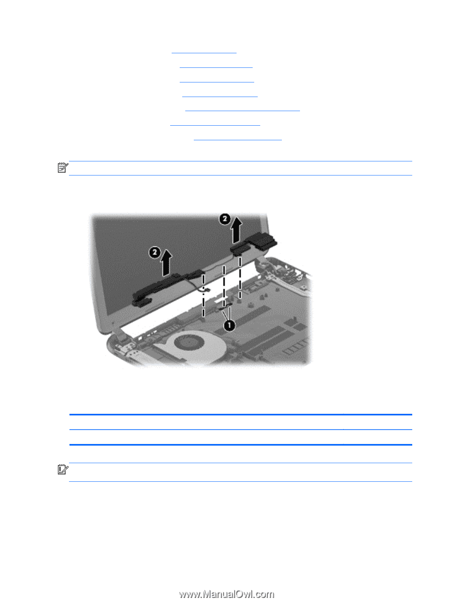
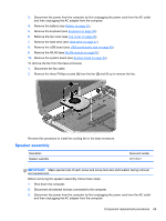
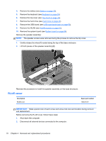
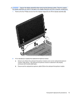
4. Remove the battery (see Battery on page 35). 5. Remove the keyboard (see Keyboard on page 39). 6. Remove the top cover (see Top cover on page 43). 7. Remove the hard drive (see Hard drive on page 47). 8. Remove the USB board (see USB board/audio jack on page 50). 9. Remove the WLAN (see WLAN module on page 51). 10. Remove the system board (see System board on page 54). Remove the speaker assembly: NOTE: The speaker screws were removed during the process to remove the top cover. 1. Gently release the wires (1) routed along the top of the base enclosure. 2. Lift both pieces of the speaker assembly (2). Reverse this procedure to install the speaker assembly on the base enclosure. RJ-45 cover Description RJ-45 cover Spare part number 700428-001 IMPORTANT: Make special note of each screw and screw lock size and location during removal and replacement. Before removing the RJ-45 cover, follow these steps: 1. Shut down the computer. 2. Disconnect all external devices connected to the computer. 70 Chapter 4 Removal and replacement procedures
-
 1
1 -
2
-
3
-
4
-
5
-
6
-
7
-
8
-
9
-
10
-
11
-
12
-
13
-
14
-
15
-
16
-
17
-
18
-
19
-
20
-
21
-
22
-
23
-
24
-
25
-
26
-
27
-
28
-
29
-
30
-
31
-
32
-
33
-
34
-
35
-
36
-
37
-
38
-
39
-
40
-
41
-
42
-
43
-
44
-
45
-
46
-
47
-
48
-
49
-
50
-
51
-
52
-
53
-
54
-
55
-
56
-
57
-
58
-
59
-
60
-
61
-
62
-
63
-
64
-
65
-
66
-
67
-
68
-
69
-
70
-
71
-
72
-
 73
73 -
 74
74 -
 75
75 -
 76
76 -
 77
77 -
 78
78 -
 79
79 -
 80
80 -
 81
81 -
 82
82 -
 83
83 -
84
-
85
-
86
-
87
-
88
-
89
-
90
-
91
-
92
-
93
-
94
-
95
-
96
-
97
-
98
-
99
-
100
-
101
-
102
-
103
-
104
-
105
-
106
-
107
-
108
-
109
-
110
 |
 |