HP Pavilion TouchSmart 14-b173cl HP Pavilion TouchSmart 14 Ultrabook HP Pavili - Page 86
Display assembly, Remove the Phillips M screw
 |
View all HP Pavilion TouchSmart 14-b173cl manuals
Add to My Manuals
Save this manual to your list of manuals |
Page 86 highlights
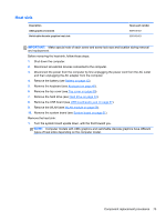
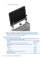
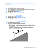
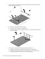
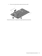
3. Disconnect the power from the computer by first unplugging the power cord from the AC outlet and then unplugging the AC adapter from the computer. 4. Remove the battery (see Battery on page 42). 5. Remove the keyboard (see Keyboard on page 46). 6. Remove the top cover (see Top cover on page 50). 7. Remove the hard drive (see Hard drive on page 54). 8. Remove the USB board (see USB board/audio jack on page 57). 9. Remove the WLAN (see WLAN module on page 58). 10. Remove the system board (see System board on page 61). Remove the RJ-45 cover: 1. Remove the Phillips M screw (1) for the RJ-45 cover. 2. Lift the RJ-45 cover (2) to remove it from the base enclosure. Reverse these procedures to replace the RJ-45 cover. Display assembly Description Spare part number 35.6 cm (14.0 in), high definition (HD), WLED, SVA BrightView TouchSmart slim display assembly, for use with HP Pavilion TouchSmart Sleekbook and HP Pavilion TouchSmart Ultrabook models 721218-001 35.6 cm (14.0 in), high definition (HD), WLED, SVA BrightView flat display assembly, for use with HP Pavilion Sleekbook and HP Pavilion Ultrabook models. The display assembly is spared at the subcomponent level only. IMPORTANT: Make special note of each screw and screw lock size and location during removal and replacement. 78 Chapter 5 Removal and replacement procedures
-
 1
1 -
2
-
3
-
4
-
5
-
6
-
7
-
8
-
9
-
10
-
11
-
12
-
13
-
14
-
15
-
16
-
17
-
18
-
19
-
20
-
21
-
22
-
23
-
24
-
25
-
26
-
27
-
28
-
29
-
30
-
31
-
32
-
33
-
34
-
35
-
36
-
37
-
38
-
39
-
40
-
41
-
42
-
43
-
44
-
45
-
46
-
47
-
48
-
49
-
50
-
51
-
52
-
53
-
54
-
55
-
56
-
57
-
58
-
59
-
60
-
61
-
62
-
63
-
64
-
65
-
66
-
67
-
68
-
69
-
70
-
71
-
72
-
73
-
74
-
75
-
76
-
77
-
78
-
79
-
80
-
 81
81 -
 82
82 -
 83
83 -
 84
84 -
 85
85 -
 86
86 -
 87
87 -
 88
88 -
 89
89 -
 90
90 -
 91
91 -
92
-
93
-
94
-
95
-
96
-
97
-
98
-
99
-
100
-
101
-
102
-
103
-
104
-
105
-
106
-
107
-
108
-
109
-
110
-
111
-
112
-
113
-
114
-
115
-
116
-
117
-
118
-
119
 |
 |
