HP Pavilion TouchSmart 14-n019nr HP Pavilion 14 Notebook PC HP Pavilion TouchS - Page 83
Service door see
 |
View all HP Pavilion TouchSmart 14-n019nr manuals
Add to My Manuals
Save this manual to your list of manuals |
Page 83 highlights
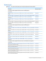
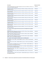
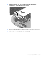
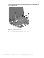
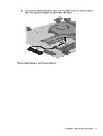
Description Spare part number AMD A8-5545M A76M (2.7 GHz/1.7 GHz, 4 MB L2, 1333 MHz DDR3L quad core, 19 W) for use 734446-501 with Windows Standard AMD A76M chipset, A8-4555M processor (2.4 GHz/1.6 GHz, 4 MB L2, 1600 MHz DDR3L quad 736822-001 core, 19 W) for use with FreeDOS and Ubuntu AMD A76M chipset, A8-4555M processor (2.4 GHz/1.6 GHz, 4 MB L2, 1600 MHz DDR3L quad 736822-501 core, 19 W) for use with Windows Standard AMD E2-3000 (1.65 GHz, 1 MB L2, 1600 MHz DDR3L, dual core, 15 W) for use with FreeDOS and Ubuntu 734447-001 AMD E2-3000 (1.65 GHz, 1 MB L2, 1600 MHz DDR3L, dual core, 15 W) for use with Windows Standard 734447-501 For computer models equipped with AMD processors and switchable discrete graphics AMD Radeon 8670M 1 GB graphics and A6-5200 processor (2.6 GHz/2.1 GHz, 2 MB L2, 1600 MHz DDR3L, dual core, 17 W) for use with FreeDOS and Ubuntu 734440-001 AMD Radeon 8670M 1 GB graphics and A6-5200 processor (2.6 GHz/2.1 GHz, 2 MB L2, 1600 MHz DDR3L, dual core, 17 W) for use with Windows Standard 734440-501 AMD Radeon 8670M 2 GB graphics and A10-5745M processor (2.9 GHz/2.1 GHz, 4 MB L2, 1333 MHz DDR3L quad core, 25 W) for use with FreeDOS and Ubuntu 734441-001 AMD Radeon 8670M 2 GB graphics and A10-5745M processor (2.9 GHz/2.1 GHz, 4 MB L2, 1333 MHz DDR3L quad core, 25 W) for use with FreeDOS and Ubuntu 734441-001 Before removing the system board, follow these steps: 1. Turn off the computer. If you are unsure whether the computer is off or in Hibernation, turn the computer on, and then shut it down through the operating system. 2. Disconnect the power from the computer by unplugging the power cord from the computer. 3. Disconnect all external devices from the computer. 4. Remove the battery (see Battery on page 42), and then remove the following components: a. Optical drive (see Optical drive on page 48) b. Service door (see Service door on page 43) c. WLAN module (see WLAN module on page 46) d. Memory module (see Memory module on page 44) e. Keyboard (see Keyboard on page 54) f. Top cover (see Top cover on page 59) g. Hard drive (see Hard drive on page 63) When replacing the system board, be sure that the following components are removed from the defective system board and installed on the replacement system board: ● Hard drive connector cable ● Power connector cable (see Power connector cable on page 86) ● RTC battery (see RTC battery on page 78) Component replacement procedures 73
-
 1
1 -
2
-
3
-
4
-
5
-
6
-
7
-
8
-
9
-
10
-
11
-
12
-
13
-
14
-
15
-
16
-
17
-
18
-
19
-
20
-
21
-
22
-
23
-
24
-
25
-
26
-
27
-
28
-
29
-
30
-
31
-
32
-
33
-
34
-
35
-
36
-
37
-
38
-
39
-
40
-
41
-
42
-
43
-
44
-
45
-
46
-
47
-
48
-
49
-
50
-
51
-
52
-
53
-
54
-
55
-
56
-
57
-
58
-
59
-
60
-
61
-
62
-
63
-
64
-
65
-
66
-
67
-
68
-
69
-
70
-
71
-
72
-
73
-
74
-
75
-
76
-
77
-
 78
78 -
 79
79 -
 80
80 -
 81
81 -
 82
82 -
 83
83 -
 84
84 -
 85
85 -
 86
86 -
 87
87 -
 88
88 -
89
-
90
-
91
-
92
-
93
-
94
-
95
-
96
-
97
-
98
-
99
-
100
-
101
-
102
-
103
-
104
-
105
-
106
-
107
-
108
-
109
-
110
-
111
-
112
-
113
-
114
-
115
-
116
-
117
-
118
-
119
-
120
-
121
-
122
-
123
-
124
-
125
-
126
-
127
-
128
-
129
-
130
 |
 |