HP Pavilion TouchSmart 15-n000 Maintenance and Service Guide - Page 92
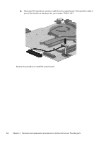
the base enclosure., Lift the right side of the system board
 |
View all HP Pavilion TouchSmart 15-n000 manuals
Add to My Manuals
Save this manual to your list of manuals |
Page 92 highlights
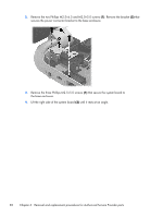
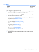
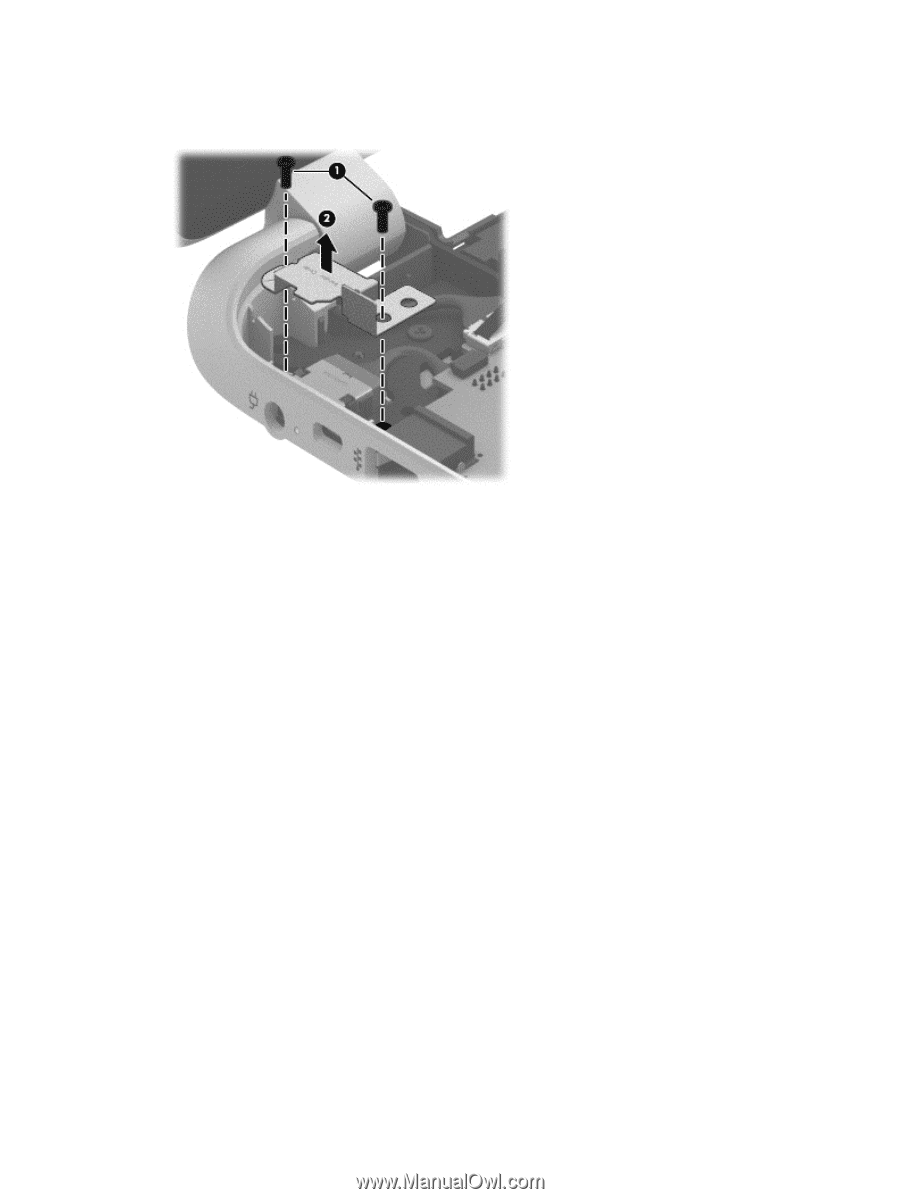
2. Remove the two Phillips M2.5×6.5 and M2.0×5.0 screws (1). Remove the bracket (2) that secures the power connector bracket to the base enclosure. 3. Remove the three Phillips M2.5×5.0 screws (1) that secure the system board to the base enclosure. 4. Lift the right side of the system board (2) until it rests at an angle. 82 Chapter 6 Removal and replacement procedures for Authorized Service Provider parts
-
 1
1 -
2
-
3
-
4
-
5
-
6
-
7
-
8
-
9
-
10
-
11
-
12
-
13
-
14
-
15
-
16
-
17
-
18
-
19
-
20
-
21
-
22
-
23
-
24
-
25
-
26
-
27
-
28
-
29
-
30
-
31
-
32
-
33
-
34
-
35
-
36
-
37
-
38
-
39
-
40
-
41
-
42
-
43
-
44
-
45
-
46
-
47
-
48
-
49
-
50
-
51
-
52
-
53
-
54
-
55
-
56
-
57
-
58
-
59
-
60
-
61
-
62
-
63
-
64
-
65
-
66
-
67
-
68
-
69
-
70
-
71
-
72
-
73
-
74
-
75
-
76
-
77
-
78
-
79
-
80
-
81
-
82
-
83
-
84
-
85
-
86
-
 87
87 -
 88
88 -
 89
89 -
 90
90 -
 91
91 -
 92
92 -
 93
93 -
 94
94 -
 95
95 -
 96
96 -
 97
97 -
98
-
99
-
100
-
101
-
102
-
103
-
104
-
105
-
106
-
107
-
108
-
109
-
110
-
111
-
112
-
113
-
114
-
115
-
116
-
117
-
118
-
119
-
120
-
121
-
122
-
123
-
124
-
125
-
126
-
127
-
128
-
129
-
130
-
131
-
132
-
133
-
134
-
135
-
136
-
137
-
138
-
139
-
140
-
141
 |
 |
2.
Remove the two Phillips M2.5×6.5 and M2.0×5.0 screws
(1)
. Remove the bracket
(2)
that
secures the power connector bracket to the base enclosure.
3.
Remove the three Phillips M2.5×5.0 screws
(1)
that secure the system board to
the base enclosure.
4.
Lift the right side of the system board
(2)
until it rests at an angle.
82
Chapter 6
Removal and replacement procedures for Authorized Service Provider parts